Table of Contents
ToggleWhen should you be more careful in selecting the right injection molding gate types?
Injection mold gate design might seem like a straightforward aspect of the molding process, but there are instances where it demands heightened attention and thoughtful consideration. While some projects might sail smoothly with a standard gate choice, others tread a more complex path. Let’s delve into the scenarios where gate design becomes a critical factor demanding extra attention.
We have listed 5 scenarios below that require extra attention to gate design:
1. Critical Aesthetic Requirements
In industries where aesthetics matter, such as consumer electronics or automotive interiors, gate design becomes an art. The gate’s location, size, and vestige should be meticulously planned to minimize visible marks on the final product. Even the tiniest imperfection can diminish the overall appeal. Achieving this level of precision demands a keen eye for detail and a deep understanding of material behavior during injection.
High Aesthetic Components
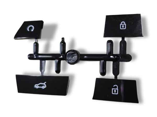
These are the parts of a car key, all crafted in one family mold. They demand a striking appearance without the need for printing or painting. They were made by 2-shot molding. The material is white to let light shine through, making the key glow in the dark.
2. Components prone to deformation
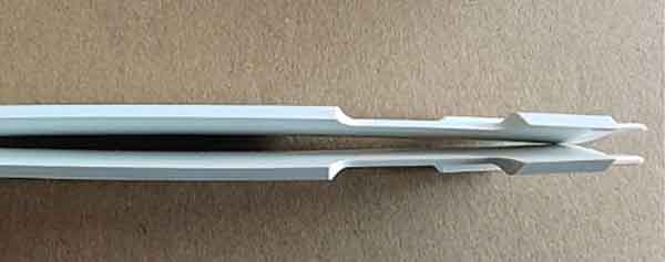
Certain plastic component designs are susceptible to warping or uneven shrinkage, resulting in deformities such as transforming a perfect circle into an oval shape. The choice of gate location can have an impact on the direction of the extent of such deformations.
In some cases, there is only one optimal choice of gate design.
3. Part designs liable to molding defects
Some part designs have a higher tendency to certain molding defects, such as weld lines. jetting, short shots, and so forth. It’s important to note that proper gate design can’t completely eliminate these defects, but it can reduce their impact to an acceptable level.
4. Large part with Multiple Gates
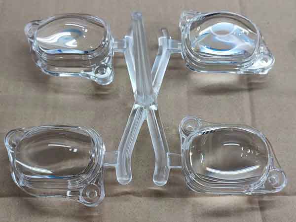
Some parts require multiple gates for effective filling. Coordinating these gates to ensure balanced flow and filling demands careful consideration. The interaction between multiple gates can impact the part’s structural integrity and visual appeal.
5. Multi-Cavity Molds
In molds producing multiple parts simultaneously, gate placement and balance are crucial. The mismatched filling can lead to uneven part quality or even mold failure.
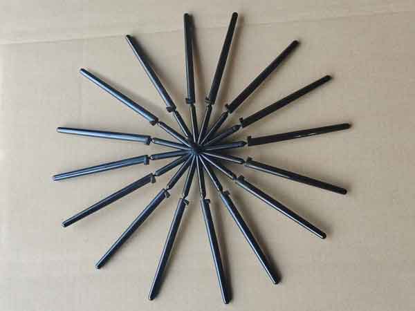
To sum up, gate design is more challenging for items with intricate shapes, high dimensional and geometrical accuracy requirements, really large items, and molds with a large number of cavities. A comprehensive understanding of flow dynamics and gate interaction is crucial in these scenarios. Additionally, computer-aided mold flow analysis is frequently employed to analyze and optimize this intricate process.
What is the injection mold gate?
An injection mold gate is a small opening in a mold through which melted plastic is injected to form a product. It’s like the entrance for the material. The gate’s size and position influence how the plastic flows and fills the mold, impacting the final product’s quality and appearance.
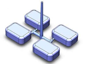
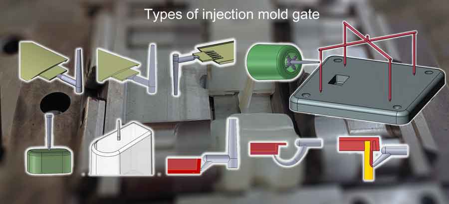
Basic types of injection mold gates
Edge Gate
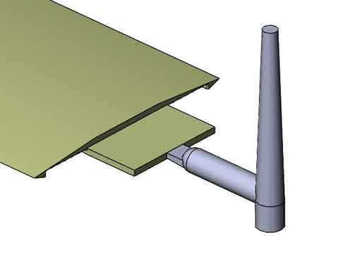
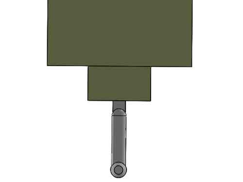
An edge gate is a gating configuration positioned at the mold’s parting line, where the two halves of the mold come together.
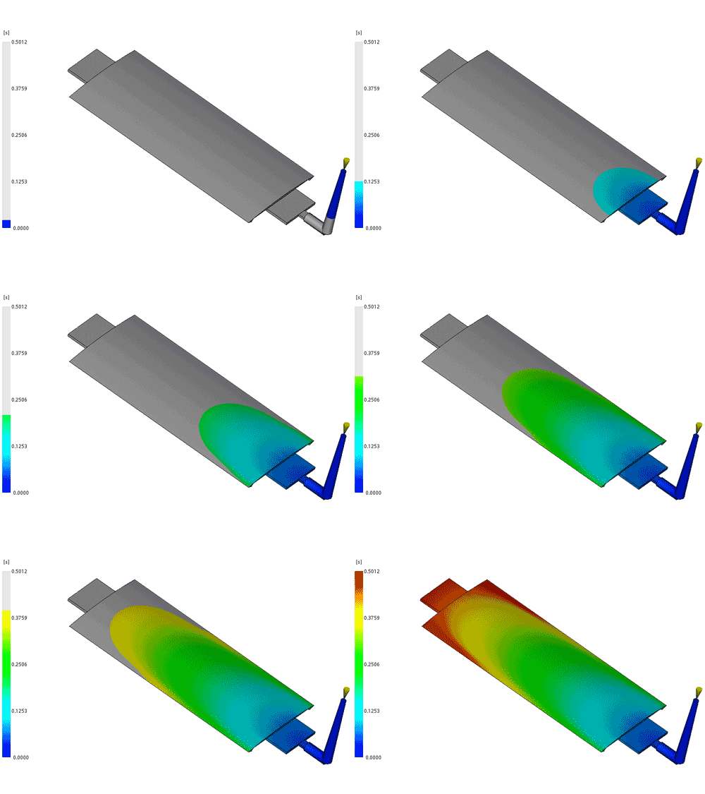
Pros:
- Ease of Machining: Edge gates are simple to machine and can be adjusted in size relatively easily during the mold trial phase.
- Less Noticeable Gate Scar: The gate scar is situated at the edge of the part, making it less noticeable. This makes it suitable for parts where only medium aesthetic quality is required.
Cons:
- Limited to Certain Part Sizes: More suitable for smaller parts with multiple cavities. For larger, single-cavity parts, an edge gate requires the use of a hot runner system.
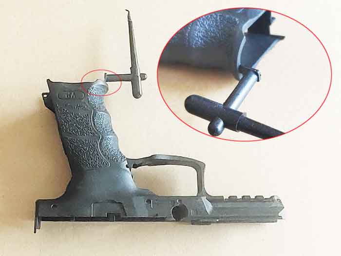
- Vestige and Appearance: Edge gating still leaves marks or vestiges on the part’s edge, making it suitable mainly for less aesthetically sensitive components. High appearance requirements might necessitate additional machining.
- Shear Stress and Jetting: High shear stress and potential jetting issues can occur in the gate area, especially for thicker-walled parts, affecting part quality.
Fan Gate
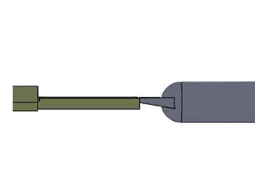
A fan gate is an evolution of the edge gate design, featuring a wider opening that spreads the material flow at a broader angle into the cavity. Its sloped bottom minimizes alterations in the cross-sectional flow front.
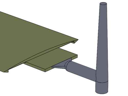

Pros:
- Enhanced Flow Dynamics: The broader opening of a fan gate improves material flow characteristics, aiding in efficient cavity filling.
- Reduced Shear Stress: Compared to other gating systems, fan gates result in lower shear stress near the gate, minimizing potential part defects.
- Mitigated Part Defects: Fan gates help decrease the likelihood of part bending and jetting issues, contributing to higher part quality.
Cons:
- Degating Challenges: Removing the gate scar left by a fan gate can be more challenging, potentially requiring additional finishing steps.
- Increased Vestige: Fan gates might leave behind more noticeable vestige or marks on the molded part compared to standard edge gates.
Tab Gate
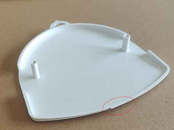
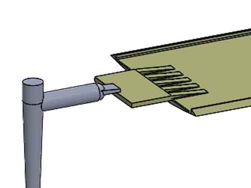
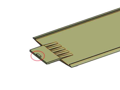
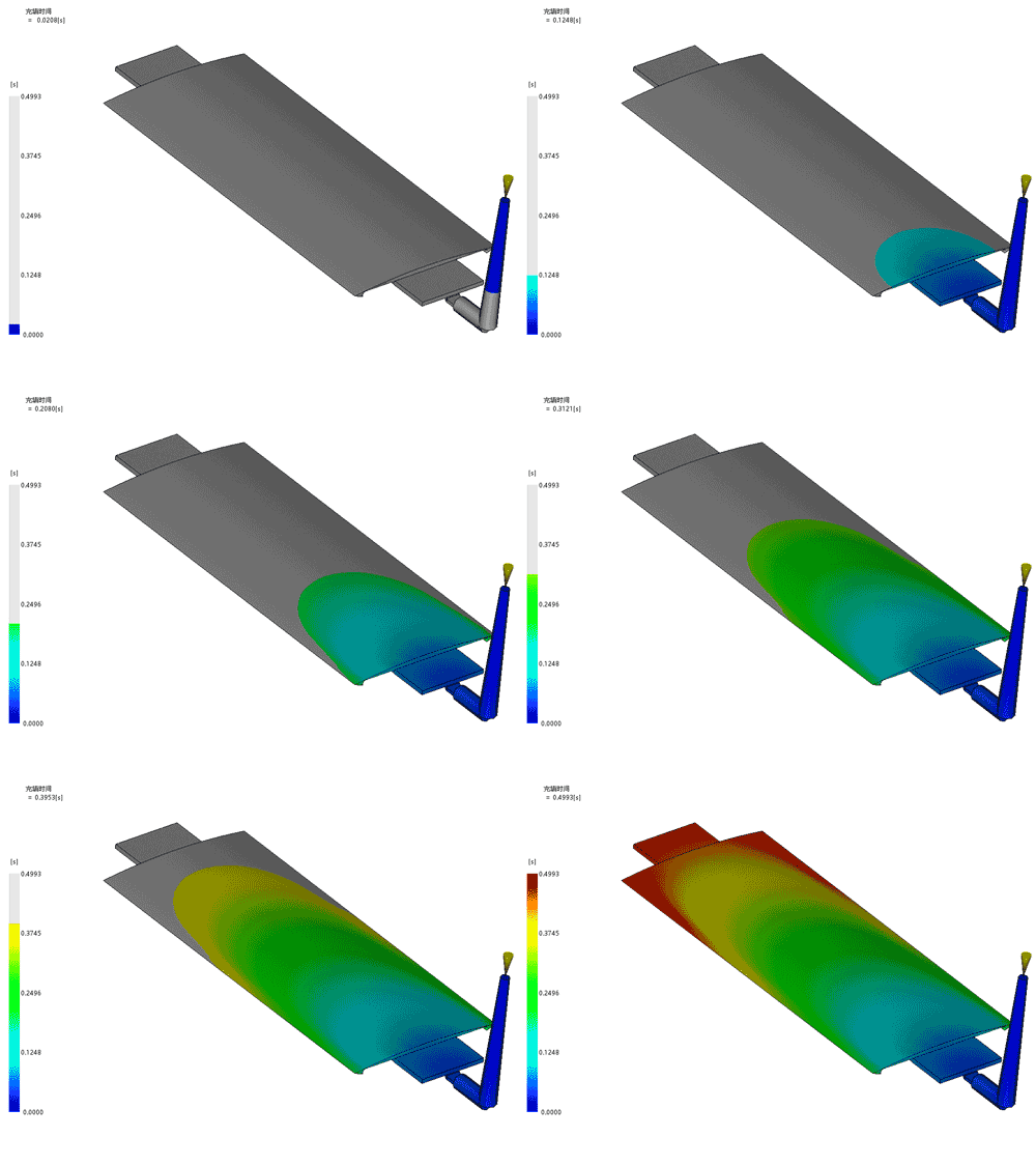
A tab gate is a gating configuration similar to an edge gate but with a distinct feature: the gate is located on top of a flat part surface. Unlike other gates that are part of the cavity, a tab gate is formed on the core side of the mold. This setup enhances material distribution and prevents abrupt direct flows into the cavity.
Pros:
- Enhanced Material Flow: The tab gate’s placement aids in smoother material flow, supporting more even cavity filling.
- Reduced Jetting Risk: By controlling the flow dynamics, tab gates lower the likelihood of jetting defects in the final part.
- Low Flow Resistance: The design of a tab gate minimizes flow resistance, contributing to efficient injection molding.
- Simplicity and Cost-Effectiveness: Tab gates boast uncomplicated design and relatively low manufacturing expenses.
Cons:
- Gate Blush Potential: Certain scenarios might lead to gate blush, requiring careful consideration of gate placement and design.
- Cleaning Challenge: Cleaning the tab feature can be troublesome. Ideally, its positioning should allow for a protrusion; otherwise, post-molding machining may be necessary.
Spoke Gate
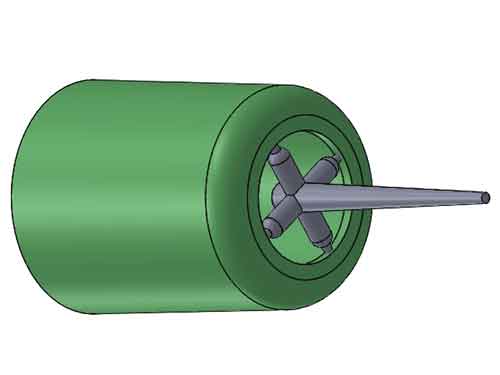
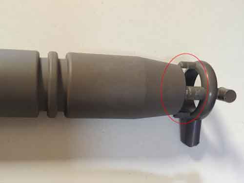
The spoke gate derives its name from its wheel spoke-like configuration. It often has four spokes for easier machining. The spoke gate is primarily utilized in tubular parts, this gating system enhances roundness.
Pros:
- Balanced Tube Filling: The spoke gate ensures more uniform filling of tubular sections, preventing distortion or ovality.
- Minimized Weldline: The flow pattern reduces the meeting of 2 flow fronts if compared to one gate design. This helps to reduce the weld lines.
Cons:
- Complex Machining and Higher Cost: The intricate design and machining requirements increase manufacturing complexity and costs.
- Scar/Vestige Formation: The spoke gate leaves four light scars that can be challenging to completely remove, potentially affecting the part’s appearance.
Pin-Point Gate
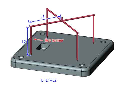
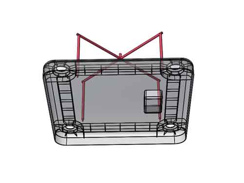
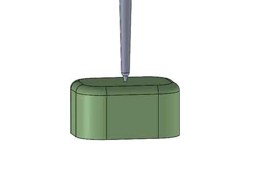
The pin-point gate (or pin gate), is characterized by its inverted cone shape ending in a sharp point. With a diameter typically ranging from 0.8 to 1.5mm, it requires a three-plate mold design to remove the sprue, runner, and gate leftovers.
The hot runner version lacks the inverted cone shape so it can work with a 2-plate mold.
Pros:
- Automatic De-gating: The pin-point gate allows automatic separation from the part during ejection.
- Minimal Gate Scar: The small gate scar often requires no post-processing, enhancing part appearance.
- Versatile Design: Multiple pin gates can be strategically placed within a single-cavity mold.Hot runners will be required if the span between gates are long.
Cons:
- Complex Mold Design: Pin-point gates necessitate a three-plate mold or hot runner, which will add expense. Hot runners are costlier than three-plate molds.
- Flow Pressure and Filling Limitations: High flow pressure loss and low filling volume make them unsuitable for large-volume parts or high filling speeds.
- Stress-Related Issues: High-speed filling can cause gate blush, flow marks, and reduced gate area strength.
- Uneven Filling: Certain part areas may experience insufficient filling due to the gate’s configuration.
Sprue gate or direct gate
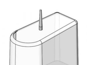
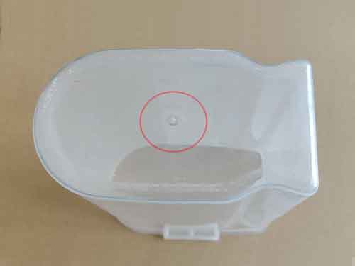
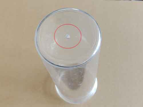
The sprue gate, also named as a direct gate, is the simplest gating system and eliminate the existance of the runner. Employed in single-cavity molds, it is positioned at the center of the part’s projection area. It has a tapered shape with the larger end located on the mold cavity side. Sprue gates are often seen in the production of plastic containers like barrels and basins.
Pros:
- Simplicity and Cost-Effectiveness: Sprue gates are easy and inexpensive to manufacture.
- Low Pressure Loss: This gate type boasts minimal pressure loss, accommodating high filling speeds and volumes.
Cons:
- Gate Scar and Blush: The sprue is usually removed with pliers, leaving a noticeable gate scar and potential blush on the opposite side.
- Shear Stress: Due to the substantial filling speed, high shear stress can occur near the gate, leading to defects.
- Unsuitable for Large Flat Parts: Inappropriate for large, flat parts due to the potential for warping and distortion during cooling.
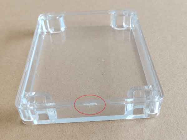
(The spure gate is quite commonly used for plastic containers, especially with transparent material.)
Tunnel or Submarine Gate
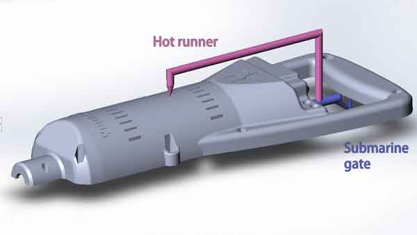
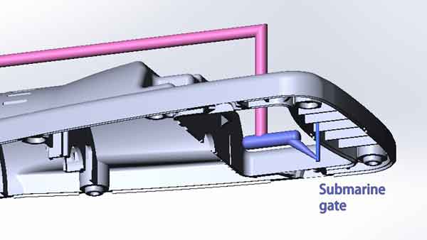
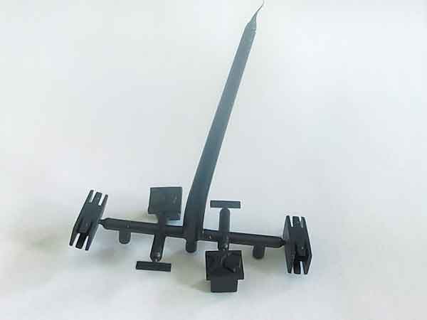
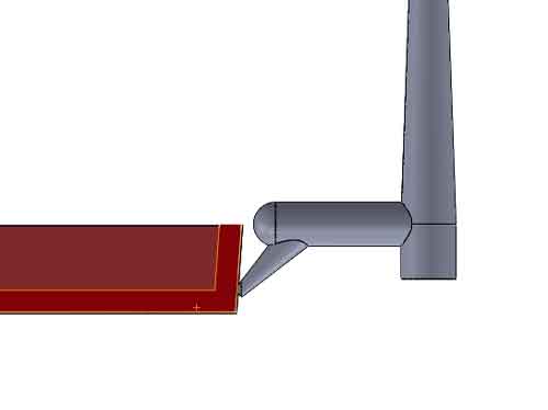
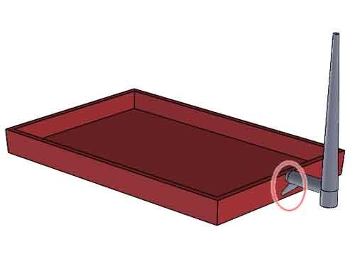
The submarine gate (or sub gate, tunnel gate) is strategically positioned beneath the mold’s parting surface. Its purpose is to relocate the gate scar to inconspicuous areas, ensuring improved aesthetics. Like pin-point gates, it boasts a small aperture. Here are the associated pros and cons:
Pros:
- Automatic De-Gating and Reduced Post-Processing: Sub gates enable automatic gate removal, minimizing the need for gate scar processing.
- Enhanced Appearance: Concealed gate scars result in improved part aesthetics as they are hidden from view.
- Design Flexibility: Similar to pin gates, multiple sub gates can be integrated into a single-cavity mold to optimize filling and flow dynamics.
Cons:
Complex Machining: Crafting the curved pathway requires machining on 2 half pieces separately, and assembling them together to form the plastic flow channel. This adds machining intricacy.
High Pressure Loss: The design is associated with notable pressure loss, potentially leading to insufficient filling in some part areas.
Possible gate blushes: there may be gate blushes near the gate area.
Sub-ejector gate
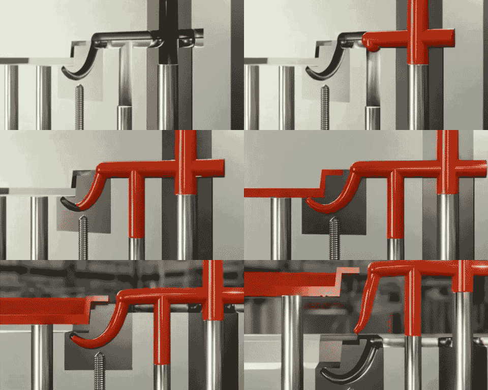
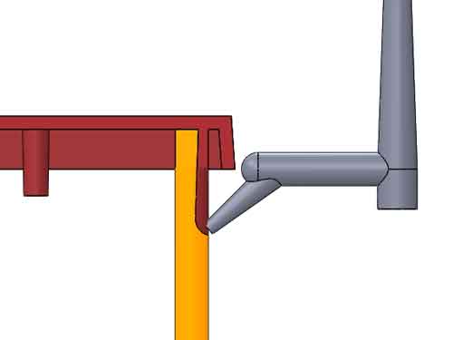
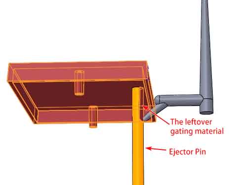
The sub-ejector gate is a modified version of the sub gate, and it’s widely favored for its simplicity in manufacturing.
In this gating system, a portion of the ejection pin is ground down to create the flow channel. The leftover gating material is removed by manually breaking it off.
Cashew Gate or Banana Gate
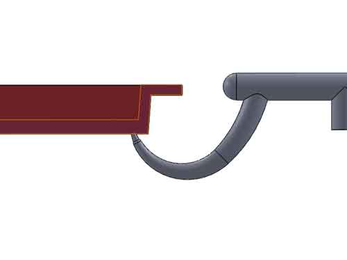
These are variations of the submarine gate, taking the form of cashew nuts or bananas. Their pros and cons align with the submarine gate and won’t be separately discussed.
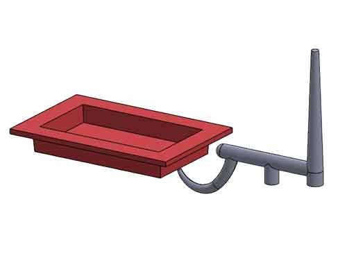
Hot Runners
In the cold runner system, material waste and limited cold runner length are concerns. Hot runners address this by eliminating sprues and keeping plastic in a molten state within channels.
What is the hot runner
Simply put, a hot runner is like an extension of the injection molding machine’s barrel piping. Essentially, It’s all about forming a high-temperature channel inside the mold. This is done using heating elements and temperature controls. Their job is to keep the plastic at the right melting temperature. In this way, we can effectively extend the flow length of the plastic.
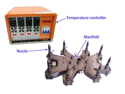
What a Hot Runner System Consists of:
- Temperature Controllers: Monitor and regulate plastic temperature throughout the system.
- Manifold: Distributes molten plastic evenly to nozzles. Notably, the manifold is not required in cases where the nozzle is at the center of a single cavity mold.
- Nozzles: These serve as the entry points for injecting molten plastic into the mold.
Types of Hot Runners:
- Pin-Point Gate: Small-diameter, minimal vestige; suited for intricate or small parts.
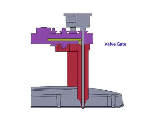
- Valve Gate: An adaptable gate type, it allows for controlled plastic flow by opening and closing. This minimizes vestige and proves beneficial for gating multiple cavities.
- Open Gate: Direct flow path, suitable for various gates, eliminates or minimizes runners.
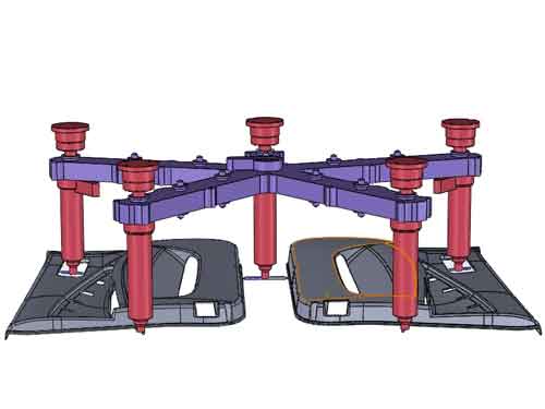
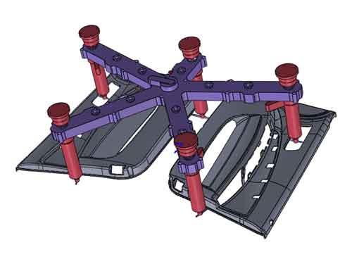
Pros:
- Flexible Gate Design: No distance constraints, versatile gate placement.
- Enhanced Part Quality: By keeping plastic molten, the occurrence of defects linked with cold slugs in runners is diminished.
- Reduced Material Waste: No cold runners, less waste and costs.
- Faster Cycle Times: No need to cool runners and sprues per shot.
Cons:
High Initial and Maintenance Costs
More Waste in Color Changes
Start-Up Time: Requires heating and stabilization before production.
Conclusion:
Choosing the right gate type is a key part of successful injection molding. From efficient hot runners to sneaky submarine and tunnel gates, each has its benefits. Think about cost, speed, and looks to find what works best for your parts. Picking the right gate helps you make great products and improve your molding process.
