Ever noticed how many everyday plastic items around you and they all have those thin and uniform walls? They’re not just a style thing or a way to save materials. These slim walls with even thickness are a big deal in how things are made through injection molding. This article is your guide to understanding the basics of wall thickness in injection molded part design. We’ll explore why it matters for how sturdy things are and how they’re actually made. Let’s dive in!
Unveiling the Role of Wall Thickness in Plastic Parts
Let’s get into the nitty-gritty of wall thickness in plastic parts. Imagine it as the width of the path through which hot liquid plastic flows. Once this molten plastic gets injected into a mold, it cools down and hardens while also shrinking. But here’s the thing: the speed at which it cools depends largely on how thick the walls are. If the path is too wide, cooling takes longer, and the plastic shrinks more. This can lead to all sorts of problems like shrinkage, air bubbles or vacuum voids. On the flip side, if the walls are too thin, the plastic hardens before filling up all the space, causing what’s called “short shots.” So, It’s all about finding that sweet spot in wall thickness to get things just right.
The Significance of Consistent Wall Thickness in Injection Molding
Picture a river flowing steadily, its width remaining relatively consistent. When a river’s width fluctuates significantly, it creates turbulence, causing eddies, impacts, and shear stress at those variations. Believe it or not, a similar principle applies to the injection molding process.
Simulation of plastic flow in the mold
During injection, maintaining a uniform flow of molten plastic is crucial. Just as with the river, variations in the width of the plastic flow can lead to problems. These issues can include uneven fills, structural weaknesses, and cosmetic imperfections. Hence, in injection molding, we emphasize the need for the wall thickness of the molded parts to be as consistent as possible. It’s all about achieving a smooth, predictable flow for a successful end product.
Choosing the Right Wall Thickness for Different Plastics
In the realm of injection-molded parts, one size doesn’t fit all when it comes to wall thickness. The ideal thickness depends on two critical factors:
The Type of Plastic Used: Each plastic material brings its unique characteristics to the table. Variations in flow behavior, strength, rigidity, and other properties mean that the ideal wall thickness can differ significantly from one material to another.
The Size of the Product: The size of the product matters—a lot. Larger products inherently demand more strength and stability, necessitating thicker walls to withstand mechanical stresses.
To simplify this decision-making process, let’s refer to a practical table outlining the recommended wall thickness for various types of plastics:
Plastic Material
Min. Thickness
Recommended Thickness of Small-sized Plastic Parts
Recommended Thickness of Mid-sized Plastic Parts
Recommended Thickness of Large-sized Plastic Parts
PA
0.45
0.76
1.5
2.4~3.2
PE
0.6
1.25
1.6
2.4~3.2
PS
0.75
1.25
1.6
3.2~5.4
HIPS
0.75
1.25
1.6
3.2~5.4
PVC
1.2
1.6
1.8
3.2~1.8
PMMA
0.8
1.5
2.2
4.0~6.5
PP
0.85
1.45
1.75
2.4~3.2
CPE
0.9
1.35
1.8
2.5~3.4
PC
0.95
1.8
2.3
3~4.5
PPE
1.2
1.75
2.5
3.5~6.4
CA
0.7
1.25
1.9
3.2~4.8
POM
0.8
1.4
1.6
3.2~5.4
Exploring Maximum Wall Thickness in Injection Molded Parts
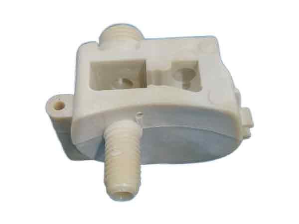
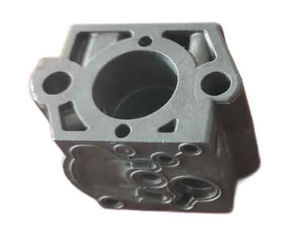
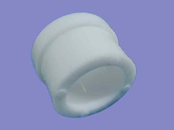
Although it is generally said that plastic parts are thin-walled, there are always many exceptions. In some applications, the limitation of thin wall must be broken:
Maximum thickness: 8.6mm
Maximum thickness: 9.2mm
Maximum thickness:10mm
Strength Matters: Plastic parts are required to have sufficient bending resistance, tensile strength, rigidity, etc.
Weight and Inertia: The product needs to have sufficient weight, moment of inertia, etc.
Local Features: The product has some local features such as protrusions and holes, and the distance between them is too close to be hollowed out.
The data recommended in the above table are only suitable values, but not absolute. Appropriately increasing the wall thickness can also obtain satisfactory quality, but sometimes requires specialmaterials, machines, and processes to do so.
Maximum thickness: 15 mm
Maximum thickness:20 mm
Reducing Regional Minimal Wall Thickness
While the above table outlines minimum thickness guidelines for various plastics, it’s important to note that these values aren’t set in stone. The plastic’s flow capacity isn’t solely determined by its type but also by factors like flow length and temperature.
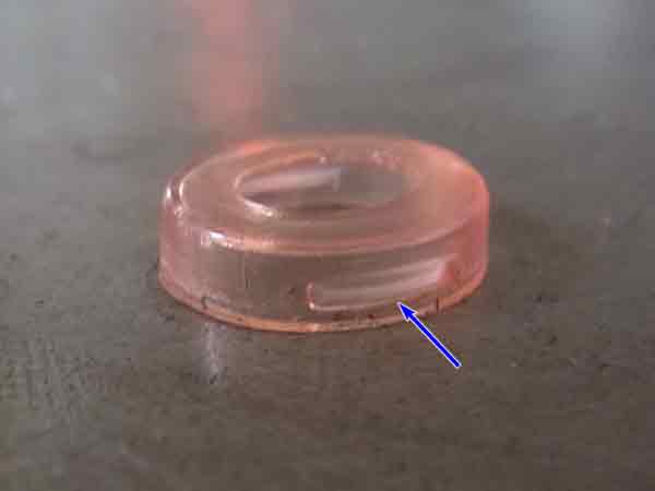
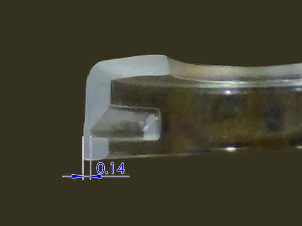
In areas near the injection gate, where the plastic remains at higher temperatures and the flow distance is short, the minimum wall thickness can often be much less than what theory suggests. For instance, consider a miniature plastic component made from PC (polycarbonate). In this case, the local wall thickness might be as thin as 0.15mm, even though the recommended minimum thickness for PC is typically 0.95mm. This underscores the idea that real-world injection molding can sometimes defy the conventional rules.
(Regional thickness can be made much smaller than recommended values.)
(A small plastic part made of PC, with a minimum regional wall thickness of 0.14mm only.)
Understanding the Flow Length-to-Thickness Ratio
Let’s dive into the concept of the Flow Length-to-Thickness Ratio. This ratio, often referred to as the flow length ratio, is a crucial metric in injection molding. It represents the relationship between the distance a plastic material needs to travel (the flow path) and the thickness of the wall, and it’s a key consideration during the mold design phase.
Think of it this way: as plastic travels within the channel, it is constantly cooled by the mold cavity walls,, causing it to solidify. The distance the plastic can effectively flow isn’t just determined by the width of the channel; it’s also influenced by this travel distance.
A typical flow ratio is between 90-270.
Now, if the flow length ratio falls short of what’s needed, it’s possible to compensate by increasing the number of injection gates. However, for product designers, knowing the basics of this ratio is generally sufficient. We won’t delve deeper into the technicalities here, but understanding its importance is vital for informed and effective design decisions.
Wall Thickness of Ribs and Bosses: A Design Consideration
In plastic product design, the outer wall thickness of plastic products serves as a fundamental parameter. However, the intricate network of ribs and bosses within the structure demands special attention during the design phase.
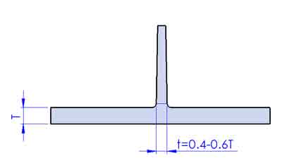
Guidelines for Ribs
1. Rib Thickness: Typically, the wall thickness of ribs falls within the range of 40-60% of the base wall thickness. However, this isn’t a rigid rule. Should you need to increase rib thickness, be prepared for potential sink marks.
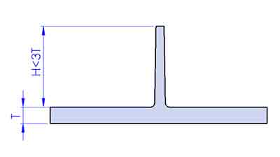
2. Rib Height: The height of reinforcing ribs is recommended to be less than three times the thickness of the base wall. Excessive height can narrow the top, making it challenging to fill and ejection of the part.
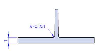
3. Rounded Bottom: It’s advisable to round the bottom of ribs with a radius of roughly 0.25 times the base wall thickness. This promotes plastic flow and prevents stress concentration.
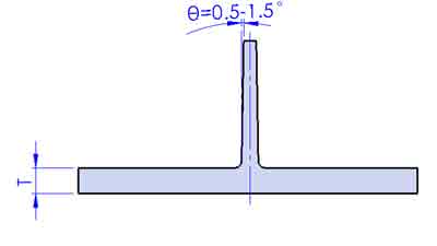
4. Draft Angle: Maintain a draft angle of about 0.5-1.5 degrees on the reinforcing ribs, when it is a polished finish.
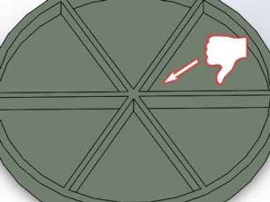
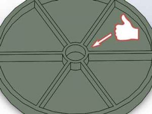
5. Avoid Overlaps: It’s best to avoid multiple ribs intersecting at the same point, as this can result in excessive thickness at the intersection.
Not recommended
Recommended
Guidelines for Bosses
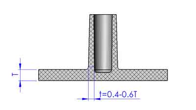
1. Boss Thickness: Similar to ribs, boss wall thickness ideally ranges from 40-60% of the base wall thickness.
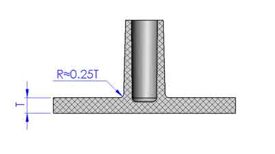
2. Rounding the bottom: Similar to ribs again, round the bottom with a radius approximately 0.25 times the thickness.
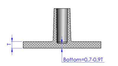
3. Bottom Wall Thickness: Consider making the bottom wall thickness slightly thinner, say 0.7-0.9 times the wall thickness, to reduce the sink marks.
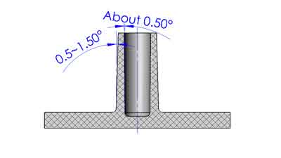
4. Draft Angle: For bosses, an external draft angle of 0.5-1.5 degrees and an internal angle of 0.5 degrees are generally recommended.
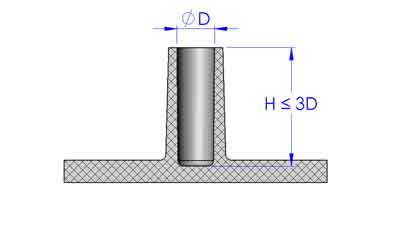
5.Maximum Depth of Holes in Bosses:
These guidelines primarily serve to prevent core pin bending or breaking due to the high injection pressure, enhancing the quality and appearance of the molded parts.
Blind Holes: It’s advisable not to exceed a depth greater than 3 times the hole diameter.
(Blind hole)
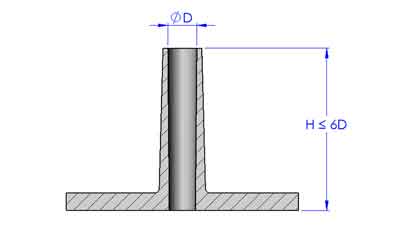
Through Holes: In the case of through holes, the depth can extend to 6 times of hole diameter. This is because the core pin can be supported on both ends.
(Through hole)
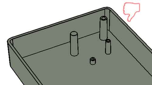
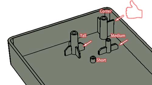
6. Structural Stability: Enhance structural stability by connecting bosses with ribs where necessary. Usually, the taller bosses requires the ribs more than the shorter bosses.
Not recommended
Recommended
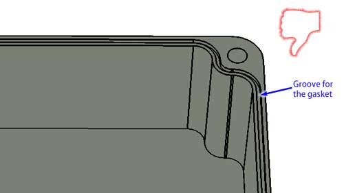
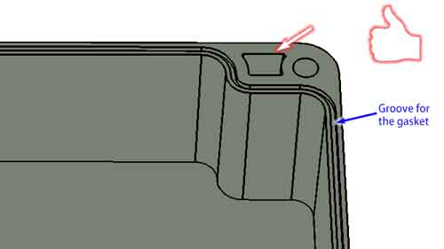
7. Placement: Ensure bosses are not placed too close to side walls to prevent integration and local over-thickness. Otherwise, try to hollow out the area that is too thick.
Keep in mind that these recommendations might need adjustments based on your part’s unique design and application. Hence, consulting with a professional injection molding service provider before finalizing your design is a prudent step.
Conclusion
In summary, injection molding involves a delicate balance between thin walls, which are typical, and exceptions dictated by strength, weight, or intricate designs. Our guidelines for ribs and bosses are essential tools for finding this equilibrium.
Keep in mind that these are flexible principles rather than strict rules, requiring adaptability and precision in your approach. In the end, successful molding lies in your ability to tailor the process to the specific demands of each project. Happy molding!