Table of Contents
ToggleWhy choose Boyan as your plastic gear manufacturer?
Gears, being high-precision transmission components, demand a lot from their manufacturers: deep knowledge of gears, advanced manufacturing techniques, and a highly responsible attitude.
Boyan meets these criteria. We offer comprehensive services that cover everything from design and manufacturing to inspection.
In the following sections, we will delve into the specifics of plastic gear dimensions and the manufacturing process. By reading this article, you’ll gain the necessary information to make an informed decision. Opting for Boyan means ensuring every aspect of production meets the highest quality standards, ensuring your needs are perfectly met.
Pros and cons of plastic gears
In general, there are both advantages and disadvantages of plastic gears. They are briefly listed below:
Advantages:
1.Lower production costs (for high volumes);
2. Light weight and low inertia.
3. Self-lubricating or operates with less lubrication;
4. Corrosion resistant (some plastics);
Vibration damping for quieter operation;
5. Can be made into complex shapes, thereby reducing the number of parts, and the size of the overall assembly.
Disadvantages:
1. Higher initial cost of the injection molds;
2. Lower load capacity;
3. Lower precision;
4. Poorer dimensional stability in high temperature or humid environments;
5. Poorer material properties in harsh environments (high temperatures, humidity, chemical corrosion, etc.).
Plastic gears are more used in applications of low speed, light load, and lower transmission accuracy requirement, and thus a larger backlash is allowed.
The parameters that determine the profile of a gear include:
- Module, which dictates the size of the teeth
- Number of teeth, which, together with the module, determines the size of the gear’s pitch circle;
- Pressure angle, typically 20°, though 14.5° is also used.
- Addendum modification coefficient, where gears with a small number of teeth generally choose a positive value, while others may opt for 0 (to adjust the center distance of gears, it can also be adjusted to a non-zero value).
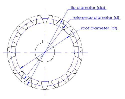
With these 4 parameters, the contour of a spur gear can be defined. For helical gears, the helix angle also needs to be determined.
Tips: For metal gears manufactured with cutting tools, standard parameters are adopted due to the standardization and serialization of the tools.
However, for plastic gears, since the molds are not made with gear cutting tools, any chosen parameters can be used. Nevertheless, for the sake of design, inspection, and other requirements, standard parameters are recommended.
Understanding these parameters is just the beginning of gear design; in-depth knowledge and extensive experience are crucial.
For manufacturers of gear molds, providing them with a detailed 3D design allows for precise replication based on the provided data, even in the absence of specialized gear knowledge. Yet, having an understanding of gear design principles remains crucial for ensuring the highest quality control.
How to ensure the machining precision of plastic gear molds
To achieve the required precision in molding plastic gears, it’s crucial to employ high-precision machining techniques such as slow wire EDM, helical mirror finishing EDM, and the use of turning and milling centers along with other advanced CNC machinery.
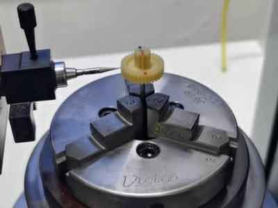
Throughout these machining operations, careful alignment and calibration of the workpiece on each machine clamp are essential to maintain concentricity.
Moreover, diligent measurement of dimensions is necessary to verify the accuracy of tool compensation. Given the inherent precision of the machinery, inaccuracies often stem from improper tool compensation. Therefore, by selectively measuring certain critical dimensions and ensuring their accuracy, it’s reasonable to infer that other dimensions will also be accurate, thereby streamlining the machining process.
A case study on manufacturing spur and helical gears
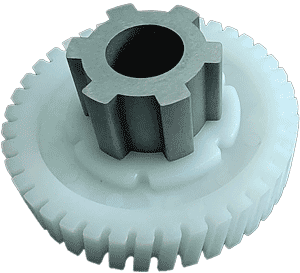
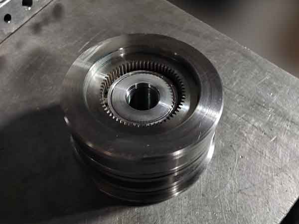
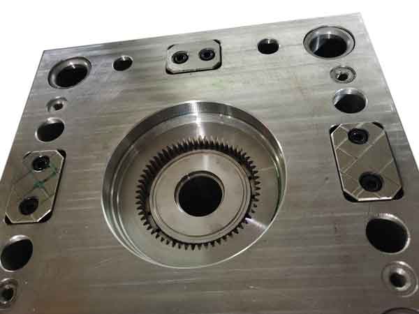
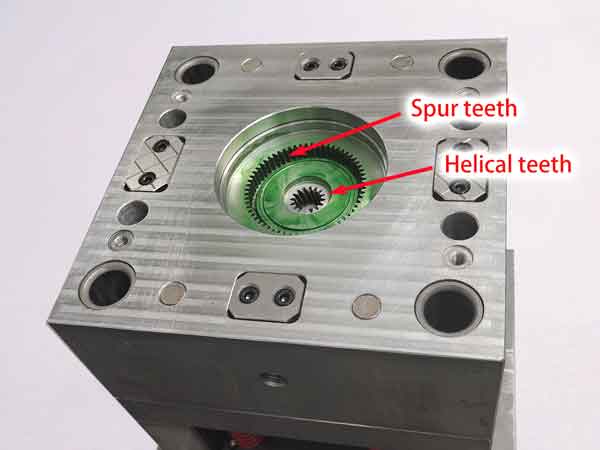
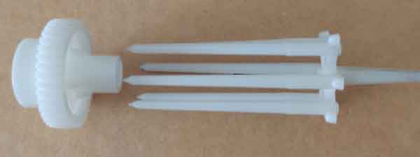
This example illustrates an effective method for manufacturing plastic gear molds, specifically for a two-level gear with smaller helical teeth and larger spur teeth.
The spur gear section is machined on an insert fixed to the mold core. Its straight teeth profiles are crafted using slow wire EDM, ensuring precise shapes.
Conversely, the helical gear section is formed by a movable mold part mounted on a bearing, allowing it to rotate according to the helix angle during demolding, facilitating the gear’s ejection. The profiles of these teeth are created with helical mirror finish EDM.
To guarantee the accuracy of the gears produced, both components forming the teeth profiles must adhere to stringent manufacturing and assembly precision standards. This includes ensuring coaxiality, flatness, parallelism, and the precision of the tooth profiles.
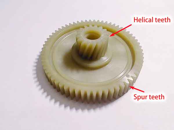
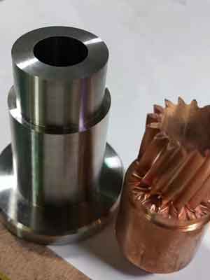
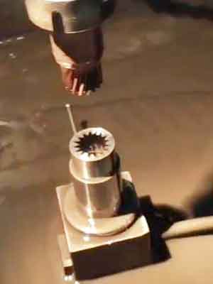
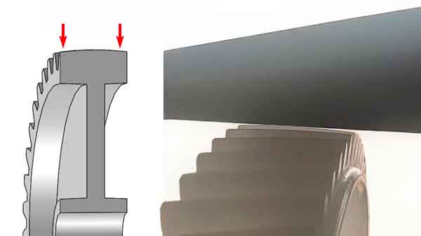
This is how the helical teeth are made in the mold:
Challenges and Solutions for Precision in Plastic Gear Manufacturing
Plastic gears are widely used in modern industry, but their manufacturing precision can be affected by various factors, making them less precise than CNC-machined metal gears. The main issues include:
Mold Manufacturing Precision When making molds, gears that don’t require high precision might use less expensive equipment, affecting mold precision. Even with high-precision equipment, manufacturing and assembly errors can occur, not to mention the potential for human error.
Injection Molding Process Parameters Temperature, speed, and pressure during injection molding directly impact gear precision, especially the packing pressure and time. For instance, a 90mm diameter gear made of POM material can have a 0.8mm difference in outer diameter when the packing pressure varies between 140MPa and 90MPa. Hence, controlling these parameters is crucial.
Uneven Shrinkage of Plastic The most unpredictable aspect of plastic gear production is uneven shrinkage. The shrinkage rate can vary between the flow direction and perpendicular to it, especially with crystalline plastics. Complex part shapes make it hard to calculate specific area shrinkage rates. Shrinkage rates near the gate are typically lower, while those farther away are higher. Design features like varying wall thickness and protrusions can also affect shrinkage rates around them.
To address these challenges, a common solution is to use multiple mold sets to incrementally adjust for precision. The first set is used to test and identify dimensional deviations. Based on these results, the second set adjusts dimensions accordingly. If necessary, a third set might be produced for further adjustments.
This step-by-step adjustment strategy effectively resolves the precision issues encountered in plastic gear production, ensuring the final product meets high precision standards. Although complex, this process is essential for manufacturing high-precision plastic gears.
Further Analysis on the Uneven Shrinkage of Gears
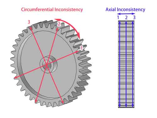
The uneven shrinkage of gears can mainly be divided into two types: circumferential direction and width direction (i.e., axial direction). That is, you measure the outer diameter at multiple points in these directions to see how consistent their measured values are.
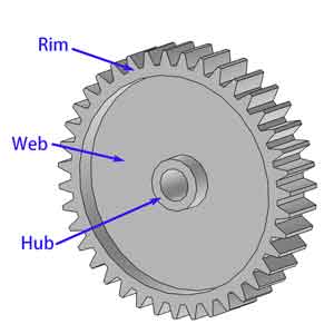
Gears are primarily composed of three parts: the rim, the web, and the hub. The design of these components significantly affects the shrinkage characteristics of the gear.
Circumferential inconsistency
Circumferential shrinkage inconsistency is mainly caused by two factors.
- First, the inconsistency in shrinkage between the direction of flow and the perpendicular direction in plastic materials can impact dimensional accuracy. This issue can be mitigated by adding more injection points.
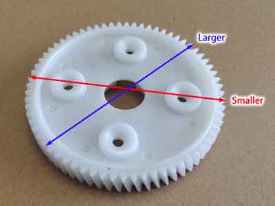
- Secondly, the localized shrinkage in the web area, due to design features such as protrusions, can be greater than in other areas, affecting the overall dimensional stability of the gear. To address this issue, ensuring uniform wall thickness in the web area or using high-pressure injection molding techniques (more than 300 MPa) can help, although the latter is more costly and not commonly recommended.
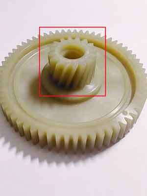
This gear features four bumps on its web area. With an outer diameter (OD) of 95.7mm, the parts right above these bumps are approximately 0.25 to 0.3mm smaller than the areas without bumps below them.
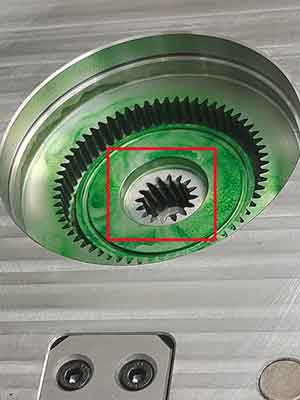
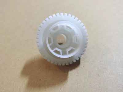
In contrast,this gear maintains a consistent wall thickness in the web area, at an OD of 38mm, its roundness (or the uniformity of the OD across identical gears) remains within 0.03mm.
Axial inconsistency
Axial shrinkage inconsistency is more complex.
On one hand, when the gear’s web is too thick, sink marks can appear in the middle of the gear face. This sinking is particularly pronounced when the internal angles of the web and rim are designed with chamfers or fillets. Although theoretically, a thinner web would be ideal, the gear’s load-bearing capacity must be considered.
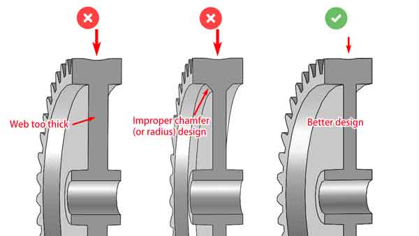
As you can see from the picture above, if the web is too thick, or if it has a chamfered (or radius) design on the inside corners, the middle section will sink more. It is better to have a thinner web, but we also need to consider the load capacity.
Another complex phenomenon is the uneven shrinkage at the ends of some gears compared to the middle part, causing the diameter to reduce at the ends. This is particularly observable in gears made of Polyoxymethylene (POM), where a slight gap can be seen on the below image.
The cause of this phenomenon is not easy to explain but might be due to the middle part shrinking less because of the restriction provided by the web below, while the ends, without such restriction, exhibit different shrinkage behaviors.
To reduce this kind of axial shrinkage inconsistency, increasing the thickness of the rim could be considered. This not only enhances the gear’s load-bearing capacity but also helps balance the overall shrinkage rate of the gear, thereby improving the overall performance and dimensional stability of the gear.
Design Tips for Enhancing Precision in Plastic Gears
Based on the discussion above, when we need to enhance the precision of gears, the following measures should be considered:
Minimize Uneven Features: Avoid creating uneven protrusions, gussets, and ribs on the gear’s web. If such features are necessary, aim to lessen their wall thickness and ensure they are uniformly spread out.
Optimize Web Thickness: A slimmer web contributes to improved gear precision, yet it’s crucial to verify that it still meets the necessary strength criteria.
Rim Thickness Matters: Pay close attention to the rim’s thickness, as it plays a crucial role in the gear’s functionality and durability.
Efficient Gate Design in Injection Molding: Gears typically require more gates in the injection mold compared to other plastic parts. A well-designed gate system can significantly reduce shrinkage and ensure uniform dimensions across different directions of the gear.
(This plastic gear’s injection mold features 6 gates and has an Outer Diameter of 38mm).
Conclusion: Predicting and controlling shrinkage in plastic gears is challenging. For many applications, a certain level of dimensional deviation is acceptable.
However, for applications with stringent requirements, be prepared to undergo several design iterations and mold adjustments. It’s not uncommon for the injection mold to be made two or three times to achieve the final plastic gear that meets the desired tolerances.
Inspection methods of plastic gears
Dimensional inspection
Modern Techniques:
The use of computerized equipment for gear inspection, such as gear profile inspectors, CMMs (Coordinate Measuring Machines), and photographic devices, is becoming increasingly common. These tools offer high efficiency and precision but come with higher costs. Consequently, manufacturers with such advanced equipment tend to decline small-volume orders.
Traditional Methods:
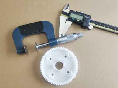
For smaller orders or when budget constraints exist, gear inspections often rely on manual tools like micrometers, vernier calipers, and runout testers. Among these measurements:
Outer Diameter (OD) Inspection: Checking the OD is straightforward if the mold’s geometry is accurate. A correct OD suggests that other dimensions are likely within specifications due to uniform shrinkage.
Common Normal Line Length: This measurement is crucial for evaluating the tooth profile’s overall accuracy, serving as a key indicator of gear precision.
In summary, while advanced equipment enhances inspection accuracy, traditional tools remain vital for smaller or budget-restricted projects, with focus on OD and common normal line length for quality assurance.
Running test
Running tests are crucial for assessing gear performance in actual devices, focusing on evaluating the noise and wear produced during operation to determine if they meet design specifications. This is essential because gears must be tested within their intended equipment context.
Noise Test: High-precision gears are expected to operate smoothly, emitting minimal and consistent noise. Low noise levels often indicate less wear and a longer lifespan, making quiet operation not just a matter of reducing noise pollution but also a sign of efficiency and durability.
Wear Resistance Test: This typically takes longer to complete. To expedite the process, testing loads can be increased to simulate the effects of long-term usage, offering a quicker insight into the gear’s wear resistance.
Among these tests, noise testing is usually prioritized due to its ability to provide immediate results. It offers a quick and reliable evaluation of gear quality.
Plastic materials suitable for gear production
The most commonly used:
- POM (acetal): It is easy to be injection molded with good dimensional stability, at the same time, it has great strength, ductility, and anti-wear, anti-corrosion, and humidity-resistant properties. This is the primary material for plastic gears.
- PA6/PA66/PA46 (nylon): It has great strength and wear resistance, but it absorbs moisture which leads to instability in dimensions. In other words, it swells while absorbing water. They are mostly used in transmission with heavier loads.
Specialized Nylon for Gears
PA66 GF40 has relatively high strength, reaching over 200 MPa, but PA46 Teflon offers even higher tensile strength.
If we opt for PA66 GF40, we need to source materials from large companies, as their products are more refined and reliable. This type of nylon is specifically developed for gear manufacturing, incorporating MoS₂ (molybdenum disulfide) and Teflon lubricants, rather than simply being PA66 with 40% glass fiber.
PEEK: This is a high-performance material comparable to metal, offering excellent heat resistance, corrosion resistance, and high mechanical strength. It also provides great dimensional stability in injection molding. However, PEEK is very expensive, and since it requires high-temperature injection molding, the processing costs are also relatively high.
TPEE: This is an elastic material, meaning it can absorb shocks and reduce noise in transmission systems.
- TPEE: this is an elastic material, which means it absorbs shocks and reduces noise in transmission.
Other less commonly used materials are:
- ABS: it is mostly used for low-end applications with lower costs, like toys.
- PC: as an amorphous polymer PC has great dimensional stability in the injection molding process, in other words, it can be molded to the shape of the mold cavity with less contraction. The disadvantages are it is a poorer self-lubricant, and it also has poorer fatigue resistance.
- PPS: this is a quite expensive material, but it has great dimensional stability and yet offers mechanical strength and durability. This is often used for harsh applications like pumps and robots.
- LCP: it is another expensive material with excellent dimensional stability and can be made to high precision, it also tolerates a high temperature of 220℃ and chemical corrosion, but it offers less strength. It can be used in watches.
Keep in mind that there are different forms to each kind of material: unfilled, reinforced with glass fibers, and filled with lubricant material (mostly PTFE or silicone), so it is rather a narrowing down process to make a choice based on each application.