Table of Contents
ToggleMeasurement of Common Normal Length in Gear Inspection Methods
When discussing gear inspection methods, measuring the length of the common normal line presents a simple and cost-effective technique widely used in gear production and reverse engineering inspections.
This method, compared to the traditional measurement of individual tooth thickness, not only simplifies the operation but also effectively avoids issues related to local elastic deformation caused by point contact, thus enhancing the accuracy of the measurements. When measuring with gear tooth vernier calipers for tooth thickness, it is essential to ensure that the calipers remain parallel to the tooth’s surface, which undoubtedly increases the difficulty of measurement. Moreover, although using CNC (Computer Numerical Control) equipment for measurement is precise, it is also costly and the process is cumbersome.
This article will start by introducing the basic concept of the involute line, gradually delving deeper into the concept of the gear’s common normal. By the end of this article, you should have a comprehensive understanding of it and be able to apply this knowledge effectively in your work.
The Basic Concept of Involute
Introduction to Involute: Simplified Understanding and Basic Knowledge
The involute, a concept frequently mentioned in mathematics and engineering, can be understood through a simple experiment: imagine we have a non-elastic thin string wrapped around a circular object (think of it as a perfect circle). As we begin to slowly unwind this string while keeping it taut, the path that the end of the string takes forms what is called an involute. In this process, the circular object is referred to as the “base circle,” and the unwinding string is known as the “generating line.”
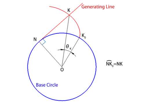
In this action, the generating line remains tangent to the base circle, and at any point on the involute, it is perpendicular to the curve. This angle, which we call the unwinding angle θ (∠KOK0), is the angle formed by the line connecting the point on the involute (K) to the center of the base circle (O) from the starting point of the involute (K0) .
It is worth noting that since the length of the string does not change, the arc length on the base circle (arc NK0) and the length of the generating line (NK) are numerically equal.
The Concept of Pressure Angle α and Its Variability
Delving deeper, let’s discuss a concept closely related to the involute—the pressure angle α. The pressure angle is the angle between the normal at any point on the involute (i.e., the line perpendicular to the involute) and the direction of velocity through that point. It is important to note that the pressure angle varies at each point along the involute, starting from zero at the beginning of the involute and gradually increasing as it moves outward.
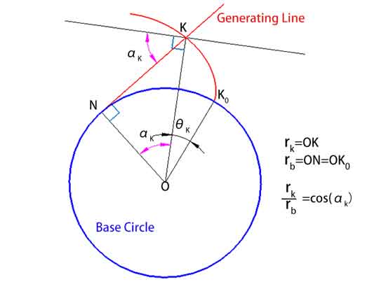
Additionally, the distance from a point K on the involute to the center of the circle, rk, can be calculated using the formula rk = rb / cos(αk), where rb is the radius of the base circle and αk is the pressure angle at point K.
Common Normal Function
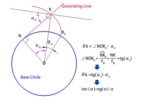
The functional relationship between the unwinding angle θ and the pressure angle α is referred to as the involute function, denoted by inv(α).
As shown in the diagram below, θk = ∠NOK0 - αk
Where, the ∠NOK0 equals thearc length NK0 divided by the radius rb, measured in arc length units, which can also be converted to degrees.
Since the arc length NK0 = NK, so = NK / rb = tg(αk)
Thus, we have θk = tg(αk) - αk
Which means inv(αk) = tg(αk) - αk
The Concept of the Gear's Common Normal
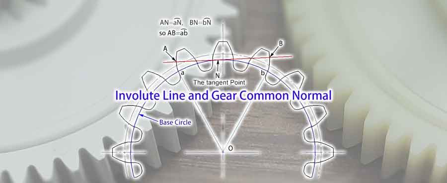
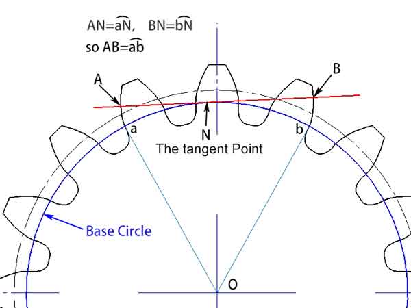
Having understood the basic concept of the involute, we can now delve into the concept of the gear’s common normal. It refers to any tangent line on the base circle that intersects the gear profiles at points separated by several teeth. Due to the characteristics of the involute, we know this line is perpendicular to the involutes that form these two gear profiles, which is why it is called the common normal.
From illustrations, we can observe that the length of the common normal (AB), nestled between these two gear profiles, is equal to the arc lengthab on the base circle. Even if the angle of the common normal changes, its length remains constant. This feature provides a significant advantage in measurements. It means that even if there is some deviation in the position of the measuring tool, it will not affect the outcome of the measurement.
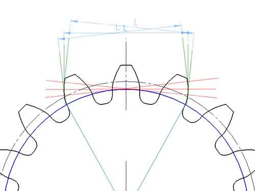
spanned tooth number
The number of teeth spanned by the gear common normal length is called the “spanned tooth number,” which can be determined from the common normal drawn on the blueprint. There is a formula to calculate it, but the calculation process can be somewhat cumbersome, making direct observation from the blueprint simpler and more straightforward. The formula is:
k = zα / 180° + 0.5
Where:
kis the spanned tooth number,zis the number of teeth,αis the pressure angle of the gear on the circumference circle, which is 20° in most casesxis the gear profile shift coefficient.
The length of the common normal can also be obtained from CAD drawings, but it can be calculated using a formula as well. For gears with a modification coefficient x = 0, the formula for calculating the spanned tooth distance is:
L = m cos α [(k - 0.5)π + z inv α]
Where:
Lis the length of the common normal,αis the pressure angle at the reference circle,kis the spanned tooth number.
The formulas mentioned above are calculated based on the modification coefficient x = 0, where the tooth thickness at the pitch circle s = zm/2, which is half of the pitch. However, if x > 0, the tooth thickness at the pitch circle increases, leading to an increase in L, and conversely, L decreases if x < 0. Therefore, measuring the length of the common normal is an effective method for gear reverse engineering, allowing for the estimation of the sample gear’s modification coefficient.
Conclusion
To keep this article concise, we will not delve into the derivation of these formulas here, but they will be covered in other articles.
We hope this article gives you a clear concept of the common normal. If you have any questions, please leave your comments below.