Table of Contents
ToggleThis is a simpler version of gear terminology and teeth calculation formulas
This post is to explain the gear terminologies and teeth calculation formulas in an easier way for beginners, and also for those who have learned gears long ago but want to pick up again quickly.
The gears have many parameters that will take a bit of mathematics and geometrical training to fully understand them. However, You do not need to go too deep into the basic concepts of gear knowledge, after you have read this post, you should be able to make preliminary gear designs or have an effective communication with gear designers.
Let’s get started from the basic gear form, the spur gears:
Table of content
1. Teeth number (z); 2. Reference circle and reference diameter (d); 3. Module (m); 4. Center distance (a); 5. Pressure angle (α); 6. Minimum teeth number (zmin); 7. Profile shift coefficient (x); 8. Summary table.
1. Teeth number (z)
This is pretty straightforward, it is the number of teeth of the gear.
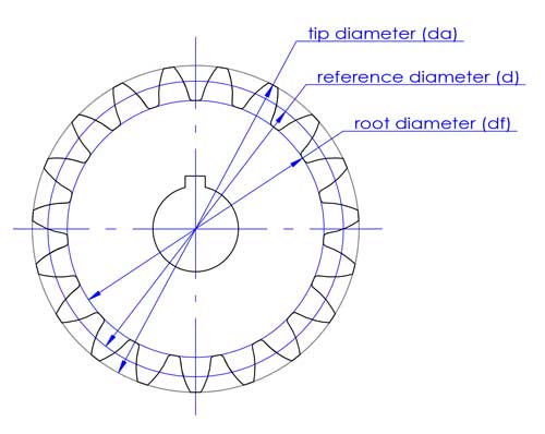
2. Reference circle and reference diameter (d)
The tip diameter (da) and root diameter (df) correspond to the top and bottom of the teeth.
The reference diameter is used in gear designing and calculation. It has direct connections with other important gear parameters like the module (m), center distance (c) and pressure angle (α).
The tip diameter (da) and root diameter (df) correspond to the top and bottom of the teeth.
The reference diameter is used in gear designing and calculation. It has direct connections with other important gear parameters like the module (m), center distance (c) and pressure angle (α).
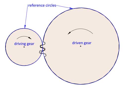
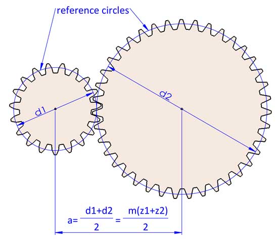
The turning of 2 gears can be considered engaged turning of 2 reference circles without slippage. The gear ratio i=d2/d1. d1 and d2 refer to the reference diameters of 2 mating gears (gear 1 is the driving gear, and gear 2 is the driven gear).
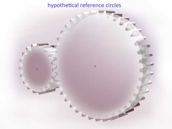
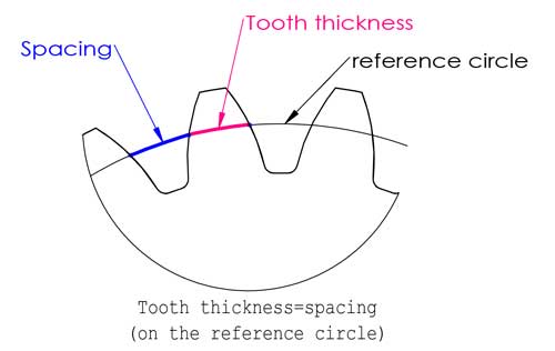
The reference circle is located somewhere between the tip and bottom of the teeth, usually it is where the tooth thickness equals to the spacing, but this is not always the case (we will talk about profile shifting later in this post).
3. Module (m)
The module is probably the most important gear parameter, and it appears almost everywhere in teeth calculation formulas. Actually, it is not so difficult to understand as you might imagine. First let’s understand what the pitch is, Pitch is the arc length between corresponding points on adjacent teeth, usually on the reference circle.
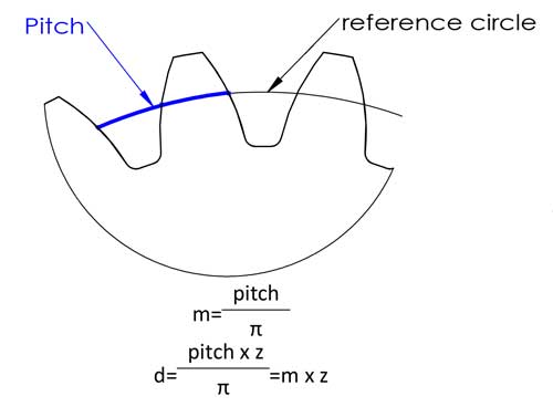
Then we have the reference diameter d=circumference/π=pitch*z/π, to make the calculation easier, we define the pitch/π as the module, and now we have the equation of d=m*z, this makes the calculation a lot easier, right? The modules have been standardized in the following numbers (unit: mm):
First series (recommeded): 0.1, 0.12, 0.15, 0.2, 0.25, 0.3, 0.4, 0.5, 0.6, 0.8, 1, 1.25, 1.5, 2, 2.5, 3, 4, 5, 6, 8, 10, 12, 16, 20, 25, 32, 40, 50
Second series (less used): 0.35, 0.7, 0.9, 1.75, 2.25, 2.75, 3.25, 3.5, 3.75, 4.5, 5.5, 6.5, 7, 9, 11, 14, 18, 22, 28, 30, 36, 45
However, for injection-molded plastic gears, there is no need to adopt these standard module numbers, since the teeth are not cut by standard tooth cutters.
Now we have the gear ratio i=d2/d1=z2/z1 (gear 1 is the driving gear, and gear 2 is the driven gear).
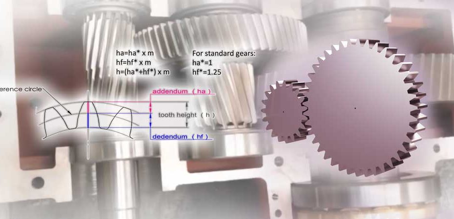
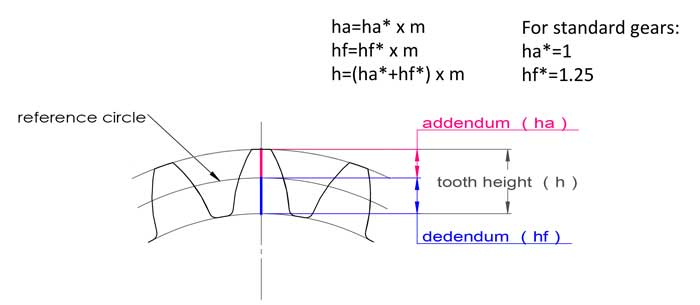
The module also has to do with the tooth height, for standard gears, the tooth height equals to 2.25*m:
addendum ha=1*m, dedendum hf=1.25*m, tooth height h=2.25*m.
4. Center distance (a)
2 meshing gears always have the same module otherwise they don’t match. Now we can come to the conclusion that a=(d1+d2)/2=m(z1+z2)/2, but it can be slightly different while making some adjustments on the gear geometries (tooth profile shifting).

Simply put, as its name suggests, it is the angle between the direction of contacting force on the contact point of the tooth and direction of motion of that point on the tooth profile.
In geometry, it is the angle between the line normal to the involute tooth profile and the line normal to its radial line.
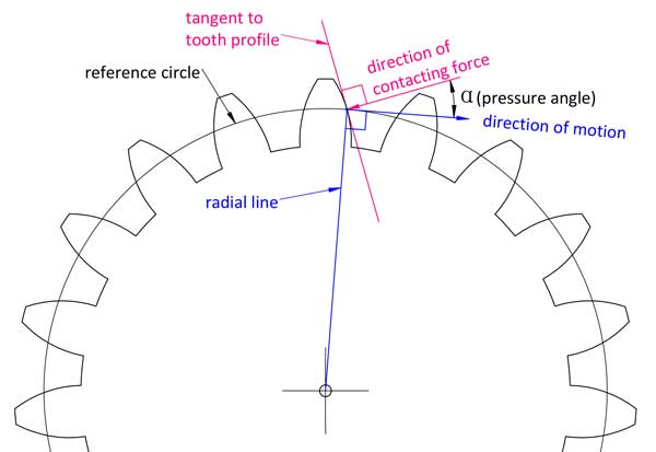
If you want to fully understand the pressure angle then you need to go deeper to understand the involute line of the tooth profile. This is just an easier way of explanation.
Different points on the tooth profile have different pressure angles, but when we talk about the pressure angle of a gear, it usually refers to that on the reference circle. Most gear use 20°as the pressure angle, some are 14.5°or 25°. 2 mating gears must have the same module and pressure angle.
6. Minimum teeth number (zmin) without undercutting in gear
You can not have any teeth number of the gear as you want. If there are too few teeth, the bottom of the teeth will be below the limit point, as a consequence, when the teeth are made by tooth cutters, an excess part of the teeth root will be cut off.
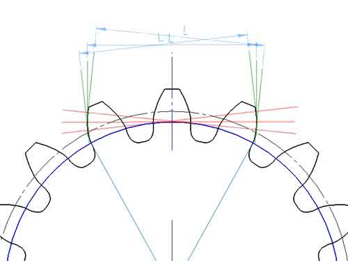
7. Profile shift coefficient (x)
Usually for the tooth profile, the teeth addendum ha=1*m, and the dedendum hf=1.25*m, however the teeth profile can be moved up or down a little bit:
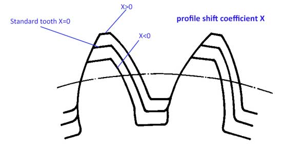
Now we have the profile shift coefficient (x). When the profile is moved upwards, the value of x is positive (x>0), and if the profile is moved downwards, the value of x is negative (x<0).
With the movement of teeth profile, now we have:
- addendum ha=(1+x)*m
- dedendum hf=(1.25-x)*m
Tooth height h=ha+hf=2.25*m, it is still the same as standard teeth.
Main reasons for profile shift are:
1) With profile shifted, we can avoid teeth undercutting with fewer teeth number. The formula is as follows:
xmin=(17-z)/17
For example, if you want to the teeth number to be 14, then X=(17-14)/17=0.176
2)Fine tune of center distance
a=[(m+x1)z1+(m+x2)z2]/2, so the center distance does not have to be (z1+z2)*m
3)Make the pinion stronger. Usually, the pinion fails prior to the gear, by adding a positive profile shift, the bottom the pinion becomes wider (while the tip becomes narrower) thus making it stronger.
In summary:
| # | Item | Symbol | Formula |
|---|---|---|---|
| 1 | teeth number | z | |
| 2 | module | m | m=pitch/π |
| 3 | gear ratio | i | i=d2/d1=z2/z1 1: driving gear, and 2: driven gear |
| 4 | addendum coefficient | da* | da*=1+x x=0 for standard gears |
| 5 | dedendum coefficient | df* | df*=1.25-x |
| 6 | profile shift coefficient | x | For standard gears,, x=0 |
| 7 | pressure angle | α | α=20° for most gears Other less used are 14.5° and 25°. |
| 8 | referernce diameter | d | d=mz |
| 9 | tip diameter | da | da=d+2Ha* x m, da=(z+2ha*) m For standard gears, da=(z+2) x m |
| 10 | root diameter | df | df=d-2Hf* x m, df=(z-2hf*) x m For standard gears, df=(z-2.5) x m |
| 11 | addendum | ha | ha=m x ha* For standard gears, ha=m |
| 12 | dedendum | hf | hf=m x hf* For standard gears, hf=1.25m |
| 13 | tooth height | h | h=m x (ha*+hf*) ha*+Hf*=2.25 for most gears |
| 14 | center distance | a | a=m x (z1+z2)/2 for standard gears a=[(m+x1)z1+(m+x2)z2]/2 for profile shifted gears |
| 15 | Mininum teeth number without undercutting | Zmin | Zmin=2ha*/sinα^2 Zmin=17 when ha*=1, α=20° |
| 16 | Minimun profile shift without undercutting | Xmin | Xmin=(17-z)/17 |
Frequently Asked Questions
Introduction to Gear Forces
In the meshing process between two gears, the force exerted by the driving gear on the driven gear can be decomposed into a normal force perpendicular to the surface of the driven gear and a tangential force perpendicular to the normal force. The tangential force does not participate in driving the driven gear, and it causes wear between the two gears. The angle at the meshing point of the driving and driven gears is largest at the beginning and end of engagement and smaller in the middle. When the meshing point is on the centerline of the two gears, it equals zero. Therefore, a smaller angle can improve transmission efficiency and reduce wear.
Relation Between Pressure Angle and Meshing Angle
The pressure angle is directly related to the meshing angle. On the other hand, a smaller pressure angle results in thinner gear roots, which reduces the strength of the gears. Therefore, it’s important to find a balance.
Industrial Standards for Gear Pressure Angles
- In current industrial production, most standard gears use a 20° pressure angle.
- Gears designed for light loads and high speeds often use a 14.5° pressure angle, which has the advantages of lower noise and higher transmission efficiency.
- Gears designed for low-speed and heavy-load applications use a 25° pressure angle, which offers higher tooth strength but at the cost of lower transmission efficiency and higher noise.
Plastic Gears
For plastic gears, any pressure angle can be chosen since standard cutting tools are not required for their manufacturing. However, for simplicity in design, it’s common to stick with these standard values.
The circumference circle is the basis for gear calculations. Its diameter is calculated as the module (m) multiplied by the number of teeth (Z). Essentially, it’s a theoretical circle used mainly for calculations, with other gear parameters derived from it.
The pitch diameter, on the other hand, is defined during the actual meshing of two gears. It’s the circle formed by the intersection of the gears’ common normal and the line connecting their centers, passing through the point of tangency. The pitch circles of two meshing gears are tangent to each other. However, the circumference circles might not always be tangent
In standard gear designs, the circumference circle and the pitch circle typically overlap. However, if the center distance is adjusted to increase backlash or if the gears have been modified, the circumference circle and the pitch circle may differ.
Yes. In standard designs, the tooth thickness and slot width on the circumference circle are equal.
However, in practical applications, to allow for some backlash while maintaining the standard center distance, the tooth thickness is made slightly thinner.
One method is to make the tooth thickness slightly smaller than the slot width on the circumference circle.
Another method is to install the gears at a center distance slightly larger than the standard.
The required size of the backlash depends on the manufacturing precision of the gears; higher precision reduces the need for backlash.
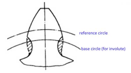
The base circle of a gear is the circle from which its involute is generated. Its pitch is the arc length between identical points on the profiles of two adjacent teeth on the base circle, so:
Pb = Db/Z.
Here, Db is the diameter of the base circle.
Or Pb = Df * cos(α) / Z = mπ * cos(α),
where Df is the diameter of the circumference circle, m is the module of the gear, and α is the pressure angle of the circumference circle.
1. For spur gears, it’s required that the meshing of one pair of teeth is synchronized with the meshing of the previous pair. This demands that their base circle pitches are equal, meaning:
m1 * cos(α1) = m2 * cos(α2).
From this, it can be inferred that the modules (m) of a pair of meshing gears do not necessarily have to be equal.
2. At the same time, the degree of engagement (contact ratio ε) is greater than 1
For gears manufactured with standard cutting tools, due to the standardization and serialization of the tools, it’s common practice to use the same module and pressure angle of the circumference circle for both gears.
3. For helical gears, it’s also necessary that their helix angles are equal, assuming their axes of installation are parallel.
The contact ratio (ε) is the length of the common normal segment between two meshing gears, which is cut by the addendum circles of the gears, divided by the base pitch (Pb) of the gear.
- When ε <1, the gears cannot function correctly because there are moments when no teeth are in contact.
- If 1 < ε < 2, there are times when only one tooth is in contact. For example, with ε = 1.63, you can imagine an average of 1.63 pairs of teeth meshing. During 37% of the transmission process, only one tooth is in engagement, while during 63%, two teeth are in engagement, leading to a greater impact during transmission.
- If ε > 2, at any given time, more than two pairs of teeth are in contact, resulting in smoother transmission.
The number of teeth (Z) on the gears is an important factor affecting the contact ratio.
For smaller gears, helical gears are often used to increase the contact ratio. However, the manufacturing cost of helical gears is significantly higher than that of spur gears.
Another method is to use a smaller pressure angle of the pitch circle, but this has a minor effect.
The lifespan of a gear is mainly determined by wear and fatigue fracture. These issues stem from various factors such as low gear precision, inappropriate backlash, poor lubrication, overheating, and more. While it’s challenging to calculate lifespan with empirical formulas, the precision of the gear and the material used are critical factors for its longevity.
Comments are closed.