Table of Contents
ToggleWhy are Injection Molding Tolerances Important?
In the production process of injection molded parts, variations in dimensions are inevitable due to influences from the mold, injection molding machine, materials, and environmental factors. Therefore, setting reasonable tolerances for product dimensions and ensuring they meet these tolerances is crucial. Appropriate tolerances can:
- Ensure that parts function correctly, especially when multiple components need to fit together;
- Guarantee product consistency and reliability;
- Reflect the manufacturing and management capabilities of the factory;
- Enhance corporate image and customer satisfaction.
Establishing appropriate tolerance values is essential. Tolerances that are too large or too small can lead to issues in product use and are indicative of a lack of knowledge in injection molding.
Sources of Dimensional Deviations in Injection Molded Parts
Dimensional deviations in injection molded parts mainly originate from two categories: molding process factors and mold factors. Here’s a detailed explanation and expansion of these factors:
Molding Process Factors
- Inconsistency in Plastic Materials: Different plastics exhibit varied flow, cooling, and shrinkage characteristics during molding. Poor consistency in materials can lead to dimensional inconsistencies within the same batch or across different batches.
- Control Accuracy of Injection Molding Machines: The precision of temperature and pressure control during the injection molding process directly affects the dimensional stability of the products. Fluctuations in temperature and pressure can lead to inconsistent final dimensions.
- Mold Temperature: Temperature control of the mold is crucial for molding quality. Uneven temperature or inaccurate control can result in uneven cooling of the parts, thereby affecting dimensional accuracy.
- Elastic Deformation of the Mold: Under injection pressure, the mold may undergo slight elastic deformation, indirectly impacting the dimensions and shape of the parts.

Mold Factors
- Manufacturing Precision of Mold Dimensions: The precision with which the mold is manufactured is a key factor in determining the dimensional accuracy of the final product. Slight deviations in the mold can be magnified during the molding process.
- Positional Accuracy of Movable Mold Components: For molds with movable components like sliders and ejector pins, the repetitive positioning accuracy of these parts inevitably impacts the consistency of the product dimensions. More details on this will be explained subsequently.
In conclusion, the issue of dimensional deviations in injection molded parts is complex and influenced by various factors, including material properties, equipment performance, and mold quality. In actual production, controlling the molding process parameters precisely, using high-accuracy molds, and optimizing material quality can effectively reduce dimensional deviations, thereby ensuring product quality and performance.
Understanding the DIN 16901 Standard
Why We Need to Understand DIN 16901
Before discussing DIN 16901, it is important to clarify why this standard deserves special attention. Tolerances for injection-molded parts have very different characteristics from those for CNC-machined parts, because plastic molding is strongly influenced by factors such as material shrinkage, mold structure, and process variation.
Among the various standards (please refer to the end of this page) used for injection-molded part tolerances, DIN 16901 is one of the most representative and widely referenced. Therefore, gaining a solid understanding of DIN 16901 provides a useful foundation for understanding the general principles and practical logic behind injection molding tolerances.
Dimension Classification
In DIN 16901, tolerances are categorized into two types: TYPE A and TYPE B, specifically designed to address the characteristics of injection-molded parts. To better understand this concept, let’s explore the process of closing an injection mold, illustrated below:
We observe that some dimensions on the plastic parts (Type B) are solely determined by the features on the upper and lower parts of the mold. These dimensions tend to change very little during the injection molding process.
In contrast, other dimensions (Type A), such as the thickness of the sidewalls and bottom, are determined after the upper and lower molds are closed. Since there might be some misalignment each time the molds close, this can lead to certain deviations. Therefore, a larger tolerance is allowed for these dimensions.
Type A dimensions also include sizes formed with the participation of moving parts like sliders and lifters.
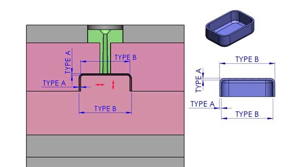
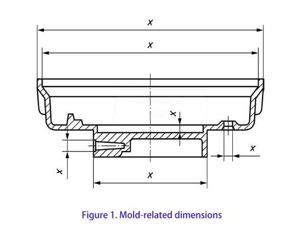
In other words, Type B dimensions are not affected by movable components within the mold. According to Figure 1 below, Type B dimensions are also known as mold-related dimensions in DIN 16901, essentially indicating the same idea.
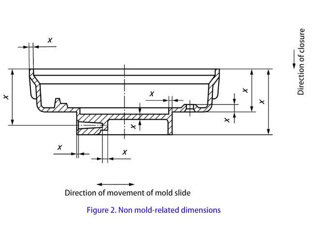
Type A dimensions however, as shown in the figure 2 below, are influenced by these movable parts, including the relative positions of the upper mold, lower mold, sliders, and lifters, which can result in minor dimensional deviations. Similarly, Type A dimensions are referred to as non-mold related dimensions in DIN 16901.
As mentioned above, the tolerances for Type A dimensions are generally larger than those for Type B, reflecting the realities of injection molding. Experienced injection molding or mold design professionals typically find it easy to distinguish between Type A and Type B dimensions.
Tolerance groups
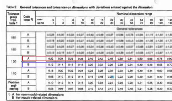
In DIN16901There are six tolerance groups: 110, 120, 130, 140, 150, and 160, with 110 being the strictest and 160 being the most lenient.
For each material, there are three possible tolerance levels. These levels are categorized as follows:
- General Tolerance: This is the default tolerance for dimensions where no specific tolerance is indicated.
- Type 1 and Type 2 Tolerances: These tolerances apply when deviations are specified for a particular dimension. You can choose from the corresponding tolerance levels based on the material and part size.
Example of Tolerance Groups for Different Materials
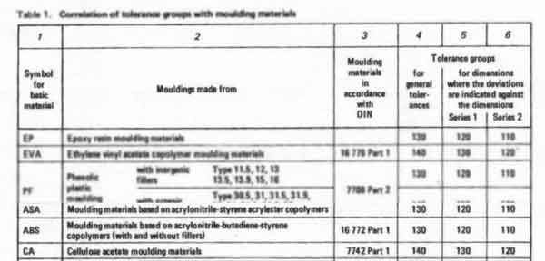
- For PMMA, the tolerance groups are 130, 120, and 110.
- For POM (without filler), when the molding length is less than 150 mm, the tolerance groups are 130, 120, and 110.
- For POM (without filler), when the molding length is 150 mm or greater, the tolerance groups are 150, 140, and 130.
- For POM (with filler), the tolerance groups are 140, 130, and 120.
From these examples, we can see several important points:
- Different plastics have different dimensional stability: Some plastics are harder to control precisely than others.
- The presence of fillers (like glass fiber, Talc, Calcium carbonate) can improve dimensional stability: Materials with fillers are generally more stable and easier to control.
Larger parts require looser tolerances: As the base dimensions of the part increase, the tolerance range typically gets larger, making precise control more difficult.
By understanding tolerance groups, manufacturers can select the appropriate tolerance levels based on material, part size, and the required level of precision.
In summary, the DIN 16901 standard provides vital guidance on dimensional tolerances for the injection molding industry. It defines different tolerance levels based on the degree of dimension impact and the type of material used, but for form and positional tolerances, other standards should be consulted.
Access to DIN 16901
The detailed content of DIN 16901 is not publicly available. Like most engineering standards, it must be purchased, so you won’t find the full document online for free. Instead, we provide our own company‑developed tolerance values, which are described in the section below.
ISO 20457: The Modern Global Standard for Plastic Part Tolerances
DIN 16901 dates back to the early 1980s, and although it is still widely referenced, it was never updated because newer, more complete standards eventually replaced its role. ISO 20457:2018 is now considered the modern, international successor to DIN 16901. It provides a clearer, more predictable, and more globally consistent tolerance system for molded plastic parts.
ISO 20457 introduces nine tolerance grades (TG1–TG9), compared with the six tolerance groups (110–160) in DIN 16901.
- TG1 is the tightest grade.
- TG9 is the loosest. In real-world production, only a subset of these grades is commonly used.
The standard also formalizes the distinction between two types of dimensions:
- W (tool‑specific dimensions) — generally equivalent to Type B dimensions in DIN 16901.
- NW (non‑tool‑specific dimensions) — generally equivalent to Type A dimensions in DIN 16901.
This makes the system easier to understand for anyone familiar with the older DIN standard.
What ISO 20457 Improves Compared to DIN 16901
1. DIN 16901 only defined size tolerances, not geometric tolerances
ISO 20457 fills this gap by adding:
- position tolerances (Table 9)
- surface profile tolerances (Table 10)
- mandatory use of ISO 1101, ISO 5458, ISO 5459
- profile tolerances for freeform surfaces
This brings plastic-part geometric tolerancing up to the same completeness level as metal-part standards.
2. DIN 16901’s tolerance system is too simplistic
DIN 16901 assigns tolerance groups based only on material type and size range, overlooking key factors that influence injection‑molding accuracy. This often results in:
- tolerances that are too loose
- tolerances that are not achievable
- disagreements between customers and suppliers
While ISO 20457 solves this by introducing a five‑factor scoring system (P1–P5):
- molding process (Table 4)
- material stiffness (Table 5)
- shrinkage rate (Table 6)
- shrinkage anisotropy (Table 7)
- production effort (Series 1–4, Table 8)
The total score determines the TG tolerance grade. Tolerances become quantifiable, predictable, and easier to negotiate.
3. DIN 16901 ignores the fact that “the farther from the datum, the larger the error”
Plastic parts accumulate error from shrinkage, warpage, and uneven cooling. These effects grow with distance from the datum, but DIN 16901 does not account for this.
How ISO 20457 solves this: It introduces Dp, the distance from a feature to the datum origin:
- position tolerances depend on Dp (Table 9)
- profile tolerances depend on Dp (Table 10)
This aligns tolerance values with real physical behavior
4. DIN 16901 provides tolerances but no acceptance rules
DIN 16901 offers tolerance tables but does not define inspection methods or acceptance criteria.
ISO 20457 adds ABF — Acceptance Conditions for Moulded Part Production (Chapter 8), which clarifies:
- what must be inspected
- how to handle deviations
- how to treat functional vs. non‑functional features
- how to manage shrinkage variation
- how to document agreements
ISO 20457 is the first standard to combine tolerance rules and acceptance rules into a complete system for molded plastic parts.
Boyan’s Simplified Injection Molding Tolerance Chart
If you are not a specialist in injection molding and only need molded parts for your product, you don’t need to spend a lot of time studying these standards. To make things easier, Boyan has created a simplified tolerance chart that serves as a practical reference for most projects.
| Nominal Dimension (mm) | 0-20 | 20-50 | 50-120 | 120-230 | 230-400 | 400-1000 |
|---|---|---|---|---|---|---|
| Very tight (±mm) | 0.02 | 0.03 | 0.04 | 0.05 | 0.10 | 0.20 |
| Tight (±mm) | 0.10 | 0.15 | 0.20 | 0.30 | 0.40 | 0.90 |
| Normal (±mm) | 0.20 | 0.25 | 0.35 | 0.55 | 0.80 | 1.80 |
| Loose (±mm) | 0.35 | 0.40 | 0.60 | 0.95 | 1.40 | 3.00 |
- For general‑precision plastic parts, the standards mentioned above work well. When a project requires even tighter tolerances—similar to LEGO components—these stricter ranges are also achievable, but only under precision‑production conditions, which naturally come with higher cost. In our chart, this level appears as the “very tight” tolerance class. Achieving such accuracy may require building a test mold before committing to the final production mold.
- Because this simplified chart does not distinguish between different materials or between different feature types (such as dimension A vs. dimension B), the values should be viewed as approximate guidelines rather than strict limits.
Understanding Injection Molding Tolerance Components
Choosing the right tolerance range is a crucial step to ensure accurate part fitting and functionality. Tolerances primarily consist of the nominal dimension and the upper and lower tolerances. Here’s a concise guide on how to select suitable tolerances for matching dimensions:
Norminal dimension, Upper and Lower Tolerances
- Tolerance is made up of the nominal dimension and the upper and lower tolerances. The nominal dimension is the specified base size, while the upper and lower tolerances define the acceptable size range around the nominal dimension.
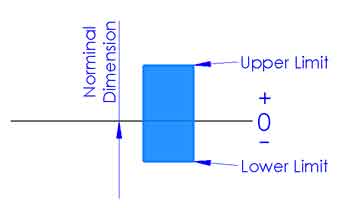
- In injection molding, the tolerance zone is often symmetrical, such as ±0.08 mm or ±0.15 mm. This gives manufacturers a clear target size to aim for, because positive and negative deviation from the target are generally considered equally likely.
Choosing Dimension Range
- By referring to tolerance standards such as DIN 16901, you can determine a suitable size range for specific materials. These standards provide recommended tolerances for different types of dimensions, such as Type A and Type B dimensions.
Determining Nominal Dimensions
- Selecting the nominal dimension is a critical step, although it is often not directly defined by tolerance standards. The nominal size should be determined according to design intent, functional requirements, and assembly compatibility. For example, if a part must fit closely with mating components, a smaller or more precise nominal dimension may be required.
Considering Practical Application
- When selecting tolerances, the part’s practical application environment should also be considered. For example, if the part will be used in environments with significant temperature variations, a larger tolerance range might be needed to accommodate thermal expansion or contraction.
Coordination and Verification
- Once tolerances have been established, they should be reviewed with the design team, production department, and quality control personnel to ensure they are both manufacturable and capable of meeting performance requirements. Where necessary, testing and validation should be carried out to confirm that the selected tolerances are appropriate
In summary, selecting the appropriate tolerance involves a comprehensive consideration of design requirements, material properties, processing methods, and real-world application environments, to ensure product quality and performance.
Let Boyan Help You Select the Right Injection Molding Tolerances
Selecting appropriate tolerances is crucial for ensuring the quality and functionality of plastic parts. Given the softness and elasticity of plastics, accurately measuring their dimensions can be challenging. We offer our expertise to help you determine the suitable dimensional tolerance range. Here’s our approach and methodology:
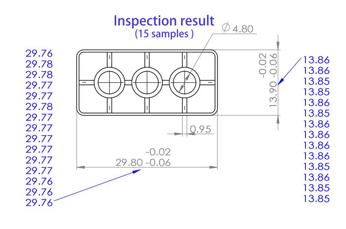
Focusing on Key Dimensions
- For key dimensions that are critical to the product’s functionality and overall quality, we establish stringent tolerance ranges. We create specialized measuring tools, such as go/no-go gauges, to ensure precise dimension measurement.


Handling Less Important Dimensions
- For less critical secondary dimensions, we typically use standard measuring tools like calipers. We also assess the fit of these dimensions using corresponding parts to ensure compatibility.
- Besides using fitting parts for measurement, we can also employ 3D-printed inspection tools for measuring dimensional accuracy. Although 3D printed products have lower accuracy, typically within +/- 0.1-0.2 mm, they are cost-effective and have short production cycles, making them suitable for applications with slightly lower precision requirements.
- Sometimes, we only guarantee the fit without providing specific tolerance values. As mentioned earlier, it’s challenging to measure plastic dimensions precisely, especially for softer materials like TPE, TPU, and silicone.

Information and Materials Required for Effective Tolerance Determination
To perform these tasks more effectively, we need the following information and materials from you:
- Specific Usage Scenarios of the Part: Understanding the environment and conditions in which the part will be used helps us more accurately determine the tolerance range.
- Samples of Matching Parts: If possible, providing samples of other parts that will be used in conjunction with the part in question can help us better assess and test the adaptability of tolerances.
Our goal is to help you determine the right tolerances in a cost-effective and efficient manner. This approach is particularly beneficial for small and medium-sized companies, as it can save time and costs while ensuring product quality.
FAQ
A common mistake for people unfamiliar with plastics is to apply metal‑part tolerances directly to injection‑molded parts.
Plastics behave very differently: they have lower stiffness, higher deformation, and their final dimensions are influenced by many molding parameters. Some amount of warpage is also unavoidable. For these reasons, plastic parts generally cannot hold the same tight tolerances as machined metal parts.
However, we can tightly control critical dimensions and achieve high precision where needed (up to ±0.02 mm). For dimensions affected by natural warpage, we focus on functional and cosmetic requirements rather than forcing unrealistic tolerances.
Most users do not need to study DIN 16901 or ISO 20457 in detail. These standards are mainly used by engineers and quality teams. For most projects, it is enough to understand what tolerance means, how it affects part function, and what tolerance ranges are typically achievable. That is why we provide a simplified tolerance chart based on real production experience.
Dimensional tolerance controls the size of a feature, while geometric tolerance controls shape, flatness, parallelism, roundness, and other form‑related characteristics. ISO 20457 places more emphasis on geometric tolerances than older standards like DIN 16901.
Yes. Features such as long thin walls, large flat surfaces, ribs, bosses, and asymmetrical geometry can increase warpage and make tight tolerances harder to achieve. Good design practices—uniform wall thickness, balanced flow, and proper draft—help improve dimensional stability.
Yes. It is common to apply tight tolerances only to critical features (snap fits, alignment points, sealing surfaces) and use standard tolerances for non‑critical areas. This approach reduces cost while ensuring functional performance.
Not really.
According to ISO 20457:2018, a part is acceptable as long as it meets its functional and usage requirements, even if some dimensions fall outside the general tolerance—unless otherwise agreed.
The only exception is when a deviation affects appearance or user perception, even if the part still functions correctly.
Yes, but achieving such precision often requires:
- High‑precision tooling
- Stable and repeatable molding conditions
- Materials with low shrinkage
- In some cases, a test mold before building the final production mold
These steps help confirm whether the required accuracy is realistic and repeatable.
Start by considering:
- The part’s functional requirements
- Whether features must fit, snap, or slide together
- Material shrinkage characteristics
- Cost versus precision trade‑offs
If you are unsure, our engineering team can review your design and recommend appropriate tolerances.
Generally yes. Tighter tolerances require:
- More precise tooling
- Stricter process control
- Longer cycle times
- Additional inspection and quality checks
For most parts, a standard tolerance range is sufficient and more cost‑effective.
Yes. If you share your CAD model and tolerance requirements, we can evaluate feasibility and suggest adjustments if needed. For extremely tight tolerances, we may recommend building a test mold first to validate the design.
Appendix: Common Standards for Injection Molded Parts
In the manufacturing and design process of injection molded parts, several standards are commonly referenced to ensure product quality and consistency. They are listed below for a quick reference:
- DIN 16901: 1982-11 — This German standard specifically addresses the dimensional tolerances and deviations for plastic molded components, applicable to a variety of plastic materials used in injection molding.
- ISO 20457:2018 — This international standard offers a comprehensive guide to dimensional tolerances for plastic molded parts, applicable to various plastic processing methods.
- DIN 16742 — It is a standard for general tolerances and acceptance conditions for plastic molded parts. It is applicable not only to injection molding but also includes compression molding and extrusion molding.
- GB/T 14486-2008 — This is a national standard of China, covering the dimensional tolerance specifications for plastic molded parts, suitable for various plastic processing methods.
- Automotive Industry Standard QC-T-29017-1991 — This specific standard for China’s automotive industry details the dimensional tolerances for plastic molded components within the automotive field.
- SAIC Standard MGR ES.22.PL.103 — This is a corporate standard of SAIC Motor Corporation Limited in China, specifically guiding the dimensional tolerances in the design and manufacturing of plastic parts within the company.
- ISO 2768 — This international standard is applicable to machined parts, including plastic components, where specific tolerances are not explicitly stated.
- JIS B 0401 — This Japanese industrial standard, similar to ISO 2768, provides guidance for dimensions not specifically indicated with tolerances on mechanical engineering drawings.
Among these standards, ISO 2768 is perhaps the most well-known. However, it is a general standard for unspecified tolerances and is not specifically designed for injection molded parts.