Table of Contents
ToggleWhat is an Injection Molding DFM (Design for Manufacturing) Report?
The DFM (Design for Manufacturing) report for injection molded products is a meticulously designed evaluation tool, specifically for assessing the design of injection molded products. The primary goal of this report is to ensure that the product design is not only suitable for the injection molding process but also optimized to reduce manufacturing costs and complexities.
Serving as a bridge between project clients and mold manufacturers, it effectively facilitates communication by visualizing design concepts into images, thereby enhancing product quality and production efficiency. In short, a DFM report is an analytical tool aimed at ensuring the efficiency and feasibility of injection-molded product designs.
Additionally, for applications with higher requirements, mold flow analysis represents another critical step. While often considered a part of the DFM analysis, it is not always necessary. Mold flow analysis aids designers in understanding the behavior of materials within the mold, optimizing both the design and the production process.
In this article, we will introduce the concept and importance of the DFM report in a clear and concise manner, supplemented with specific examples. Our goal is to demonstrate how a DFM report can aid in achieving the optimal match between design and production, leading to improved efficiency, reduced costs, and enhanced product performance.
The Role of an Injection Molding DFM Report
The DFM (Design for Manufacturing) report for injection molded products plays a crucial role in the product development and manufacturing process. Its main functions can be summarized as follows:
Confirming and Optimizing Product Design: The DFM report analyzes the feasibility of a design in the manufacturing process, ensuring that product designs meet manufacturing requirements. It also explores potential areas for optimization in the product design, significantly enhancing the final product’s quality and consistency.
Optimizing Mold Design Plans: DFM analysis examines different mold design options to ensure the best choice is made in terms of quality and cost efficiency.
Shortening the Product Development Cycle: DFM analysis helps identify design issues before production, avoiding time-consuming redesign and rework during the production phase, thus accelerating the product’s time to market.
Enhancing Collaboration Between Design and Production: The DFM report fosters communication and collaboration between designers and production teams, helping both parties better understand each other’s needs and constraints to achieve the best design solution.
Assessing the Competence of Mold Manufacturers: Not every mold manufacturer is familiar with the potential problems and risks in product and mold manufacturing, and some may not be adept at creating DFM reports. The quality of their DFM reports can represent varying levels of expertise and skill. Thus, it serves as a good method to assess the capabilities of mold manufacturers.
Typical Contents of a DFM Report
A standard DFM (Design for Manufacturability) report for injection molded products typically includes the following elements:
In the following sections, we will elaborate on each of these elements, supplemented with practical examples to illustrate their application and importance in the design of injection molded products. This approach will provide readers with a deeper understanding of the value of a DFM report and how these analyses can be utilized to enhance the efficiency of product design and the manufacturing process.
Gate type and locations
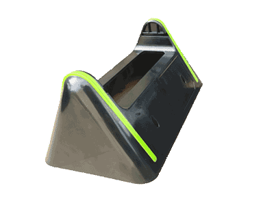
This section clarifies the paths and locations through which the material enters the mold, playing a key role in the overall quality and molding effect of injection-molded products.
Proper gate design is crucial for avoiding common defects such as warping, weld lines, and gate scars.
Note:
- In this case, we positioned the gate on the side of the mold near a corner rather than in the middle. This placement significantly reduces part warping, as gates in the center tend to cause warping on both sides, affecting the flatness.
- Additionally, we used a banana gate, placing the gate scar on the bottom surface, making it hidden during assembly and reducing the need for manual trimming. This design approach considers both the aesthetic appeal of the product and manufacturing efficiency.
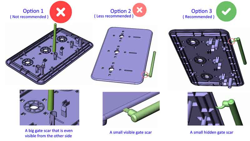
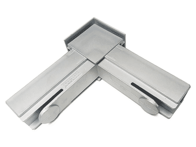
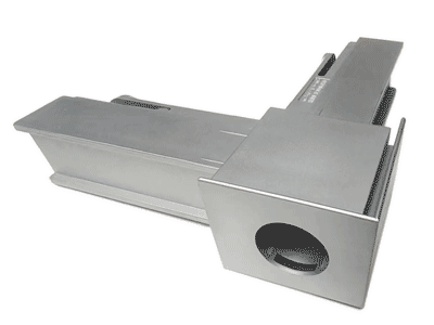
Rationale Behind Choosing Banana Gate
To further explain why the banana gate option was chosen, let’s examine a comparison of three injection molding design options illustrated in the following figure:
Note:
Option 1 – Direct Gate/Sprue Gate Option: This basic design type has a significant downside: it leaves a large gate scar at the center of the product, which can even be visible from the other side, commonly referred to as “gate blush“. Due to this aesthetic issue, this option is generally not recommended unless the product has no appearance requirements.
Option 2 – Side Gate/Edge Gate Option: This design is more feasible but still has drawbacks. Although the gate scars are smaller than those left by direct gates, small scars remain on the product’s edges. These can be visible after assembly, making this design less than ideal.
Option 3 – Banana Gate Option: This design effectively hides gate scars after assembly, thus being the generally recommended approach. However, it is important to note that breaking the gate and ejecting the part can be somewhat challenging with a banana gate, and it also presents higher flow resistance.
Given that the sprue is located at the center of the mold, option 2 and option 3 are generally more suitable for a two-cavity setup to avoid excessively long runners. However, for larger products where a single-cavity setup is preferred to save costs, a hot runner system might be necessary to address the issue of long runners due to the gate being on one side of the product.
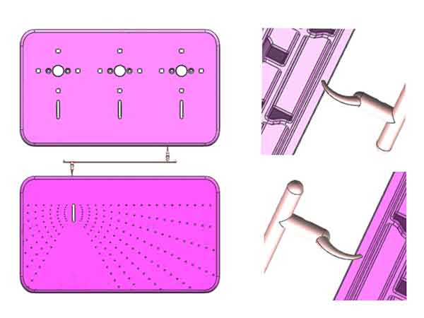
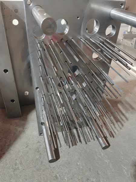
Ejector pins type and locations
Ejector pins play a crucial role in smoothly releasing the molded product from the mold. The selection of their types and precise locations significantly impacts the integrity and surface quality of the product.
- A key consideration during the design phase is whether the ejector pin marks are acceptable on the product’s surface.
- It’s essential to ensure that the product can be smoothly ejected from the mold without causing any aesthetically displeasing whitening of ejector pin marks or other forms of damage.
Proper configuration of ejector pins is vital to maintain the product’s integrity and appearance during the demolding process.
Note:
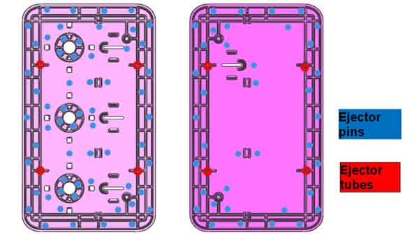
- Since the ribs, and bosses (any feature with vertical walls) will create eject resistance, the eject pins will be designed close to these features to balance the resistance. This will avoid surface distortion (keeping them flat).
- The more ribs the part has, the more ejector pins need to be allocated to balance the rib resistance force.
- Ejector tubes (similar to ejector pins but hollow inside) will be placed on the bosses with holes.
Parting Line Placement
The parting line, as a crucial juncture where the injection mold halves meet, primarily affects the product’s appearance, particularly through the potential formation of line marks. With long-term use and wear of the mold, these line marks may become more pronounced. Therefore, it is advisable to position the parting line in areas where it has minimal impact on the product’s appearance.
Additionally, since the parting line is where the mold closes, it can also affect the precision of the product’s dimensions. Specific impacts on dimensional accuracy can be found under the type A dimensions section in the injection molding tolerances guidelines.
Example 1
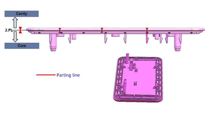
Note:
For parts like this panel, choosing the location of the parting line is relatively simple and direct. Opting for a position on a stepped flat surface helps avoid the creation of line marks and is also less susceptible to mold wear.
Example 2
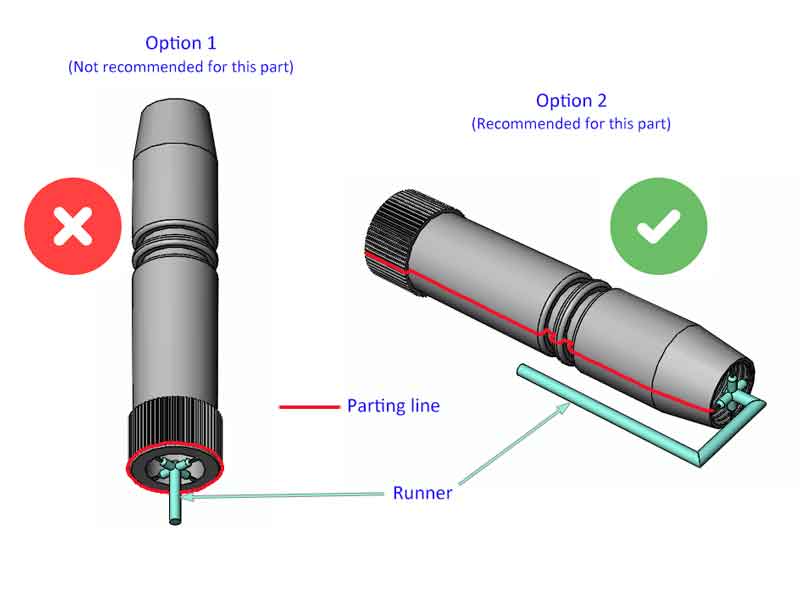
Note:
For this component, designing the parting line is somewhat complex. Typically for tube-shaped plastic parts, the standard approach (Option 1) places the parting line at one end surface. However, given the length of this part (requiring a very tall mold) and the need to maintain minimal or no draft angle on the outer diameter (as a draft angle would noticeably alter the size at one end), positioning it horizontally in the mold becomes a more suitable option, thus favoring Option 2.
To prevent the tube from becoming oval-shaped or bending, a spoke gate has been designed onto the end surface. A drawback of Option 2 is the extended runner, leading to material waste and the potential for cold slugs. To mitigate this, adopting a hot runner design could be a beneficial solution, counterbalancing the issues associated with the longer runner.
Placement of Lifters and Sliders
In dealing with plastic parts featuring undercuts, the use of lateral sliding mechanisms such as lifters and sliders is essential. Their positioning must be specifically highlighted in the DFM report.
Similar to the parting line, lifters and sliders, as moving components, can create line marks on the product. It’s crucial to ensure that their placement is acceptable in terms of the product’s appearance and functionality.
Additionally, these components can also affect the dimensional accuracy of the parts, an impact akin to that of the parting line.
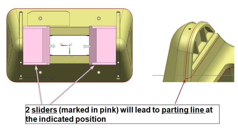
Note:
From the example in the above image, it is evident where the line marks created by the slider will appear. However, these line marks can be made very subtle and hardly noticeable.
Yet, if the product is to be produced in large quantities, the wear on the mold will gradually make these marks more pronounced. Therefore, this issue needs to be taken into consideration.
Wall and rib thicknesses analysis
The thicknesses of walls and ribs significantly impact injection-molded products:
- Uneven or inappropriate wall thicknesses can lead to issues like warping, uneven shrinkage, or stress concentration during the manufacturing process.
- Proper wall thickness is crucial for ensuring the structural strength of the product while also guaranteeing uniform material flow and cooling within the mold, thereby preventing defects.
- The design of rib thickness should be in harmony with the primary wall thickness to maintain the overall strength and stability of the product, as well as to optimize material use and production efficiency.
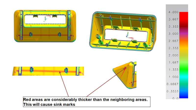
Note:
As shown in this example, since the ribs are located on a slanted surface, it inevitably results in some areas having thicker walls than others. This uneven thickness tends to lead to the formation of sink marks in these areas.
Although it’s possible to compensate for this during production by increasing the injection pressure and holding time, some degree of sink marks remains, as was confirmed in subsequent production runs.
Draft angles analysis
The draft angle is a critical aspect of injection-molded product design, primarily affecting the demolding process. An appropriate draft angle ensures that the product can be smoothly and completely released from the mold after production, minimizing surface damage or deformation.
If the draft angle is not set correctly, it might lead to the product sticking to the mold during ejection, increasing production difficulties and the risk of damage. Therefore, designing the correct draft angle is vital for ensuring product quality and enhancing production efficiency.
Most modern design software includes draft angle analysis features, which can display the draft angles of various areas using colors and numbers for easy visualization.
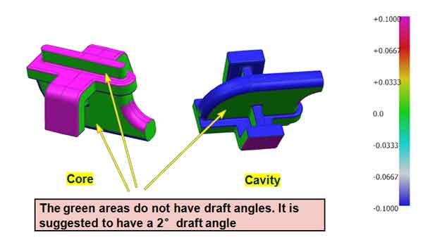
Note:
From the example shown in the image, it is evident that if the green section (the part without a draft angle) has a certain height, it is essential to add a draft angle to it. However, if the height of the green section is very low, it can be disregarded.
Possible optimization for the part design
At the conclusion of the DFM report, based on the preceding analysis, focused improvement suggestions are provided for product design, particularly regarding adjustments in wall thickness and draft angles.
Additionally, product users are required to evaluate the feasibility of gate design, ejector pin layout, and parting line settings based on the mold design proposals mentioned in the report. This process aims to ensure that the overall design meets production requirements and quality standards, facilitating an effective and efficient production workflow.
Mold Flow Analysis (MFA)
Mold flow analysis is a critical tool for simulating and optimizing the plastic injection molding process. By modeling the flow, cooling, and solidification of plastic within the mold, it helps identify potential production issues such as gas traps, warping, stress concentration, or insufficient filling.
This analysis allows for the optimization of mold design and injection parameters before actual production, ensuring product quality and increasing production efficiency. Mold flow analysis is significant for reducing the number of trials, shortening product development cycles, and lowering production costs.
However, mold flow analysis also involves additional costs. It is not necessary for all products, especially those with simpler structures. The decision to conduct mold flow analysis should be based on specific circumstances, considering the product’s complexity, production scale, and cost-effectiveness.
Generally, a mold flow analysis report includes the following contents:
Next, we will explain the content in the report related to potential injection molding defects that might occur in the parts.
General part information (the part weight and size, the material to be used with a specific grade).
Recommended processing (molding parameters, like pressure, temperature, etc.)
Fill time (this will include an animation of the filling process).
Filling contour (it looks like a geographical contour map).
Pressure at V/P switchover (meaning switching from volume control to pressure control).
Pressure at the end of fill.
Flow Front temperature.
Bulk temperature at end of fill.
Clamp Force (this will suggest the tonnage of the injection machine to be used).
Air Traps (Tendency of air bubbles).
Weld Lines.
Volumetric shrinkage at ejection.
Sink index (the tendency of sink marks).
Temperature part at the end of cooling.
Deflection (the tendency of warpage, bend, and distortion).
Conclusions and suggestions.
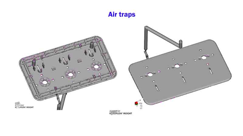
Air Traps
Air trap refers to areas within the mold where air gets trapped during the injection molding process. This trapping can lead to defects in the final product, such as voids or incomplete filling, as the trapped air prevents the plastic material from occupying the entire cavity effectively.
Note:
In this example, we can see that this part has a low tendency for air traps, which means it should be good for production.
Weld lines
The Weld Line indicates the potential locations in the molded part where two or more flow fronts of molten plastic may converge. This convergence can create a line or seam, known as a weld line, which might be weaker and less aesthetically pleasing than the surrounding material, potentially affecting the part’s structural integrity and appearance.
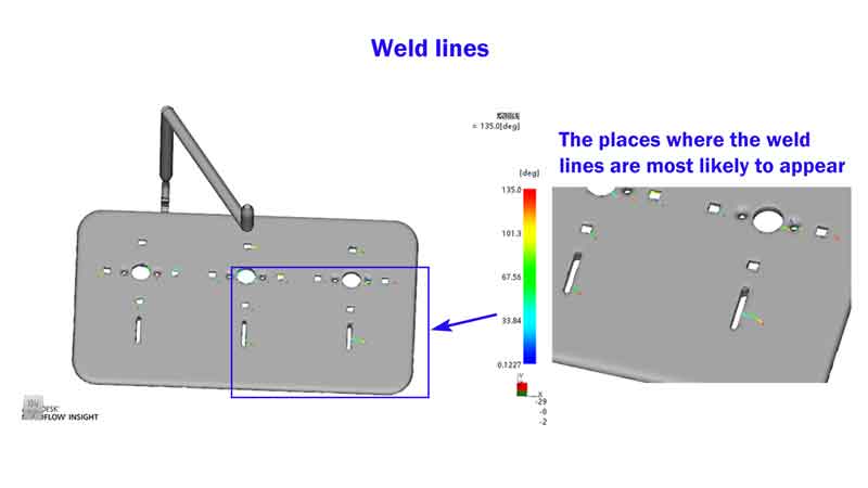
Note:
This part has a moderate tendency to form weld lines. If the material’s color and glossiness are not appropriately chosen, visible fusion lines will appear on the surface.
Sink index
The Sink Index in the report quantifies the likelihood of sink marks forming on a molded part. These marks typically occur in thicker areas where the material shrinks as it cools, leading to depressions or indents on the surface.
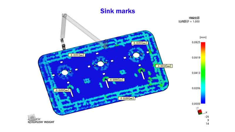
Note:
Based on the example depicted in the image, the predicted sink amount is ≤0.0218mm. This indicates that the wall and rib thicknesses are well-designed, and the sink marks fall within an acceptable range.
Additionally, for a visually appealing appearance, here are the advised sink amounts for various types of surface finishes:
- For a textured surface: ≤0.10mm
- For a painted surface: ≤0.05mm
- For a plated surface: ≤0.03mm
Deflection
The Deflection refers to the likelihood of a molded part warping or bending. It predicts the degree to which a part might deform, typically due to uneven cooling, material shrinkage, or internal stresses during the molding process
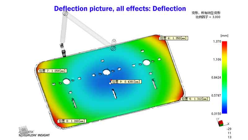
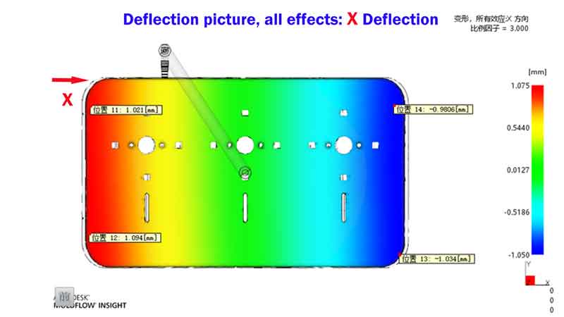
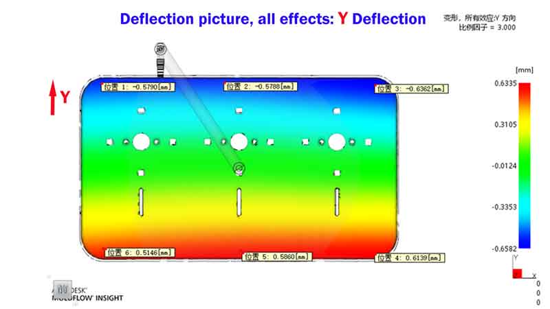
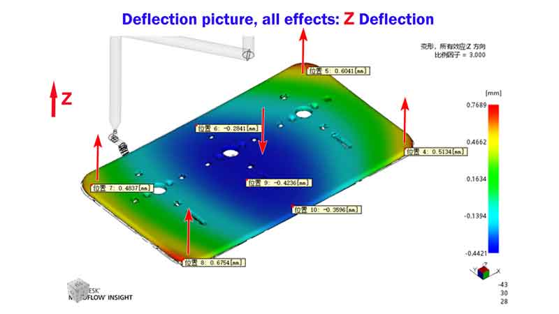
Note:
In this example, the focus should be on the Z-direction deflection, which refers to the warping deformation of the part. However, based on experience, such panel warping can be minimized by increasing packing pressure and time, a fact that was confirmed in subsequent production runs.
It’s important to note that many mold flow analysis software tools are not always accurate in predicting the extent of part warping. Relying on experience is still crucial for effective analysis.
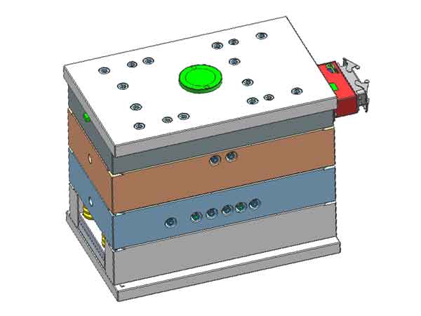
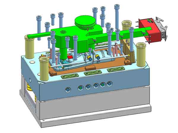
Mold drawing
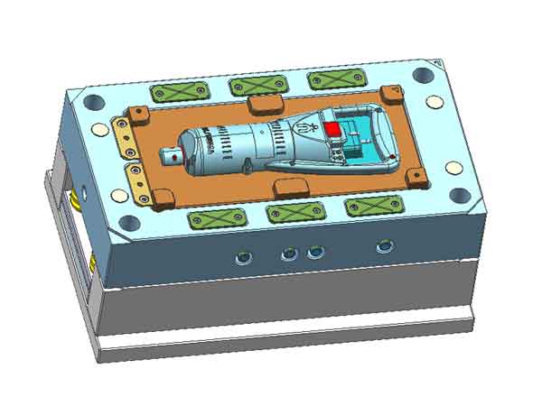
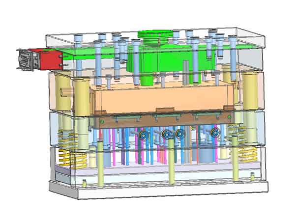
Please note that the purpose of the DFM is not to delve into the intricate details of the mold, but to succinctly present the most crucial information. This approach helps you concentrate on the key aspects while also saving time in report preparation.
For a comprehensive view of the mold, it’s advisable to request the mold drawing.
The mold drawing is especially valuable for any future repair needs. It contains all the dimensional data necessary for CNC machining of the mold components.
Conclusion
In conclusion, through the analysis steps outlined above, potential risks can be largely anticipated, allowing for the identification and improvement of existing issues. This process also enables the establishment of a basic design plan before production, making subsequent work more organized and systematic.
However, it’s important to note that the analysis from 3D design software is not entirely accurate, but it nonetheless offers significant reference value.