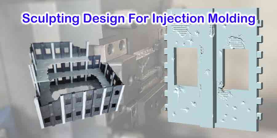
When it comes to plastic toys, scale models, and some household items, a sculpture-style design is needed.
This post is a brief description of how to do digital sculpting design for plastic products and their injection molds, and how to convert the stl to step files
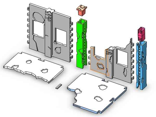
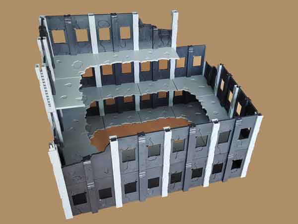
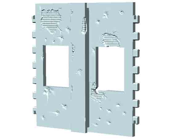
We have designed this modular terrain for a customer. As shown in the below image, there are 9 different parts to form different combinations. There are 2 walls without windows that not shown in the image, so there are 11 kind of parts in total. They can be attached and detached just like lego components.
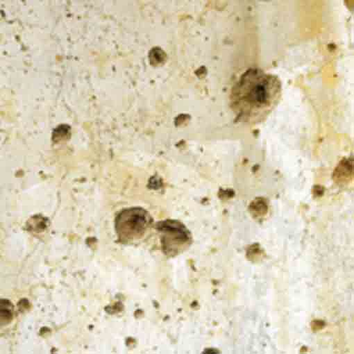
After the initial production run for Kickstarter funders the custome wants to upgrade the design, to make the parts look more like real worn-out walls.
Software used to create the 3d model
This requirement is a bit unusual for designers. In plastic products, most product designs consist of regular geometric shapes, such as flat, 2 and 3-dimensional surfaces. Designers usually use UG (or Pro/E, Creo) for their designs.
Created by UG
However, when it comes to sculpting style designs, each design may consist of hundreds of thousands of small facets. When using UG, the designer needs to create each tiny detail by hand, this would be too much to handle.
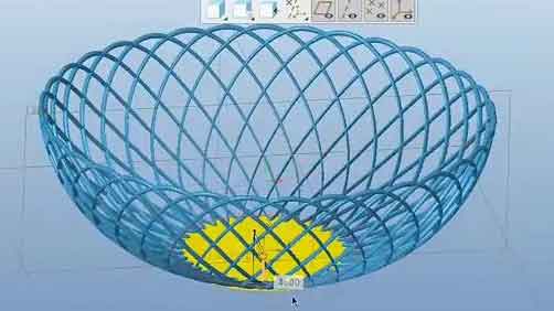
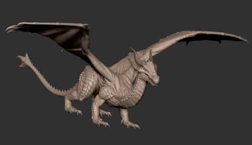
The software that can serve this purpose are Rhino, Maya, 3DS Max, and Zbrush. Among them, ZBrush is the most appropriate software to be used, it is just designed for digital sculpting.
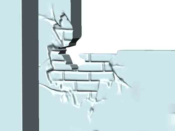
Created by ZBrush
How to work with the ZBrush designer
Working with the ZBrush designers was not an easy task. We needed to give them detailed instructions on what we wanted the product to look like.
Many of the designers are art graduates who have received good training in art and design. However, they may not know much about this specific product, so we still need to be quite involved in the design process.
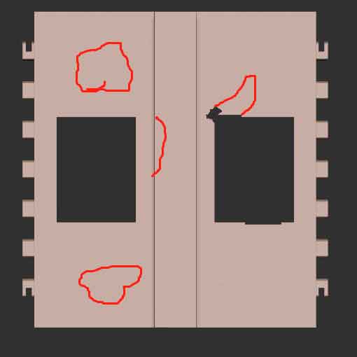
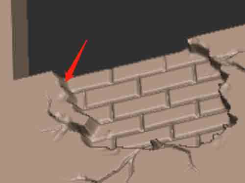
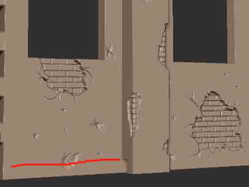
We used a lot of diagrams, pictures, and verbal conversation to convey the conceptual ideas to the designer.
(Pictures used to explain to the designer)
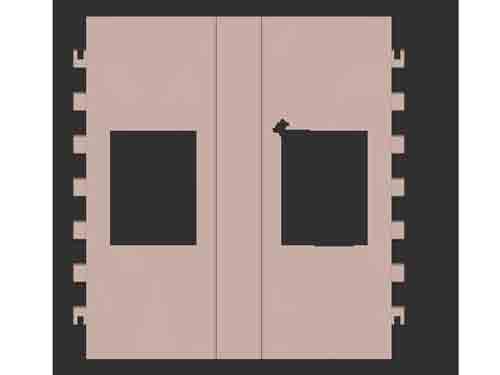
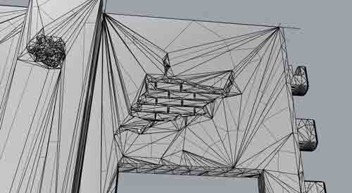
During the design process, the designer kept sending us screenshots to show the progress. This was to ensure that we wouldn’t find out too late that we had to start over again.
(Pictures sent by the designer for confirmation)
In general, we spent no less time and effort than the designers themselves. In addition, we tried several other designers until the last one finished the job the way we wanted.
How to convert stl to step files
Now comes the hard part, and that is converting the stl file to the step format.
The file format created by ZBrush (or similar software) is stl, which is ok for 3D printing, but it can’t be used for mold making.
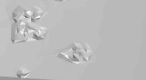
There are several application that can do the file conversion but not for so complicated designs. For example, Rhino does have the ability to convert stl to step automatically, but the files it creates consist of tens of thousands of triangular surfaces, and even flat areas consist of them. Secondly, Rhino merges small triangle faces into larger ones because it can not deal with too many of them (preferably under 30,000 faces), so a lot of small details were lost.
(step files created by Rhino)
The flat surface is made up of triangle faces.
Smaller triangles are merged into larger triangles
The correct way to convert files is to use Geomagic and UG. Geomagic will do the prelimiar jobs (like rounding off the sharp edges between the small facets), and then UG will do the final conversion.
Most designers working with ZBrush don’t know how to convert, so we found another designer to do the job.
This transition process is labor intensive for the designer and is not automatic. The time spent on it is probably 1.5 to 2 times the creation of stl file.
(Finished file in step format)
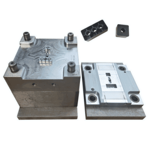
This file is ready for mold making
Rounded off sharp edges
The inspection of finished files
We don’t know many details, but the designer needs to check and fill up the broken faces, and modify the original design if there is not enough draft angle on the side surface.
So the inspection criteria will be:
No broken faces, you will find out once the file is imported to UG;
Proper drafting on the side surface, this can be checked by UG as well.
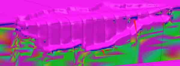
Drafting inspection done by UG
We have extensive experience in precision injection molding, please contact us when you have a need.