Common Injection Molding Defects that Customers Should Know About

The most common injection molding flaws

Identifying and Preventing Injection Molding Defects in Manufacturing

Successfully executing plastic injection molding demands extensive expertise and knowledge. The process involves numerous elements, including mold design, machine settings, the molding procedure itself, and the characteristics of the material. Improper handling of these aspects can lead to various injection molding defects.

Initiating a plastic molding project requires thorough communication with your mold maker. It’s crucial to identify potential injection molding defects beforehand. Mold makers might overlook minor defects or deem them acceptable, potentially leading to issues during mold manufacturing.

Engaging in Design for Manufacturability (DFM) and mold flow analysis can effectively address these challenges, ensuring a smoother molding process.

The Main types of injection molding defects

The main types of injection molding defects are:

1. Sink marks, 2. Flashes, 3. Gate blush, 4. Weld line, 5. Voids and bubbles, 6. Silver Streak. 7. short shots. 8. floating fibers. 9. Jetting.

Sink marks

Sink marks are unwanted depressions on the surface of injection-molded parts. They occur because during the injection molding process, the surface cools and solidifies before the interior, and in thicker sections, the interior continues to cool and contract after the surface, causing downward pulling and stretching on the surface.

They often appear in areas with thicker wall sections, excessively rapid transitions in wall thickness, or at the intersections of ribs, bosses, and outer walls.

The main issue caused by sink marks is aesthetic disturbance, but sometimes they can also lead to functional problems, especially when high precision and flatness are required.

sink mark on an ABS part
sink mark caused by a rib
sink mark caused by underneath bosses
Sink mark caused by underneath bosses

If the surface requires high gloss paint, sink marks become more pronounced. In the images below, the products show a significant difference in the visibility of sink marks before and after painting.

This issue also applies to plastic products with mirror-polished surfaces and high-gloss materials.

shiny surface is more sensitive to sink marks

For some products with excessively thick walls, increasing packing pressure and packing time may not solve the sink mark problem. In such cases, the only solution is to choose materials with relatively lower shrinkage rates.

Cause:

Sink marks occur because during the injection molding process, the surface cools and solidifies first, while the interior continues to cool and contract afterward. During the packing phase of injection molding, where the nozzle continues to supply molten plastic into the mold cavity to compensate for plastic shrinkage.

However, this additional plastic cannot fully compensate for its shrinkage, resulting in downward pulling on the surface.

If the plastic part has thin and uniform wall thickness, the downward shrinkage on its surface is consistent, so there won’t be noticeable marks of collapse. However, if there are uneven transitions in wall thickness or if the wall thickness is too thick, causing uneven and significant shrinkage, localized collapse marks will be visible on the surface.

Design Tips for Avoiding Sink Marks

Sinks marks are often the consequence of improper design. Here are 3 typical designs that will cause sink marks:

  1. The rib is too thick compared to the outside walls.

Improper design: the rib is the same thickness as the wall, or even thicker.

rib too thick will cause sink mark quite noticeable

Improved design: make the rib smaller than 0.75x  or better to be 0.6x of the wall thickness, this will alleviate the sink mark.

less thick rib will alleviate the sink mark

2. The transition in wall thickness changes too rapidly

Uneven wall thickness will cause sink mark
smoother transition of wall thickness to reduce sink marks

Try to core out the thick area (so it also has thinner walls), or if this is not possible, add a slope between the thick and then area, so the sink will not be so steep and noticeable.

3. The wall is too thick.

wall too thick will cause sink marks

Always try to avoid thick walls in plastic parts design if possible.

Remedies:

  • Optimize part design (please see above);
  • Increase the packing pressure and time;
  • Lower the mold and molten plastic temperature;
  • Put the gate in the thick-walled section and enlarge the gate size, so as to allow better material compensation in the cooling and solidifying process;
  • Conduct mold flow analysis before starting making the mold.
  • Change the material which is less sensitive to shrinkage.

Flashes or too noticeable parting line

Flash are irregular excessive material (usually in the form of thin-film) on the plastic parts that escape from the mold cavity. They usually appear along the parting line or any other place where there is a gap between moving parts inside the mold.

flashes on an ABS part
Slight flash
too noticeable parting line
Too noticeable parting line

Flashes have an unpleasing appearance, it causes the edge to be unclean.

unclean edge caused by flash
Unclean edge
improved part with less flash
Improved

Cause: An injection mold consists of an upper mold and lower mold when they are pressed together form the enclosed cavity. However there may be a slight gap between them due to inaccuracy of machining, or because of the inside pressure overcome the clamping force. At the same time, there are moving components like sliders, ejector pins in the mold, they all have slight gaps around them. The gap is totally allowed and even helpful for the gas vent. However, when the gap is greater than the limit of the viscosity allows of the molten material, it will leak into the gap and form the flashes. The impact of flash is mostly aesthetical.

Remedies:

  • Increase the precision of mold manufacturing to have smaller and consistent gaps in moving components;
  • Use a bigger injection machine (with a higher tonnage) so as to get greater clamping force;
  • Lower the packing pressure and temperature;
  • Change to higher viscosity material (less flowability).

Gate blush, or sometimes simply called as blush, is the scar-like, cloudy discoloration near the gate area. It has an inconsistent appearance than the other area. As the name suggests, many of them have a dull appearance, however, some may be mixed with brighter (more glossy) area, and they usually appear in the pattern of circular or fan-shaped, depending on the gate type and flow direction of molten resin inside of the cavity.

gate blush on a black nylon part
gate blush on a white ABS part
circular gate blush behind a direct gate

Some might mistakenly refer to “gate blush” as “gate scar” or “gate marks” if they’re not familiar with the precise terminology. However, “gate scar” actually refers the residual plastic that is not thoroughly cleaned or removed in the gate area of an injection molded part, making “gate blush” the more accurate term to use.

Causes: Gate blush is mainly caused by incorrect designs of gate type, size, and location. You should avoid a drastic change of flow direction near the gate, since this will produce excessive shear stress around this area. However the gate design is usually a compromise of all considerations, there are many other limits, but the mold design must keep this into consideration in the mold design.

Other reasons are too high injection filling speed, improper mold temperature, and the properties of the chosen resin.

The too high viscosity of the resin (or poorer flowability), which will also lead to higher shearing stress.

Remedies:

  • Slow down the injection filling speed.
  • Adjust the mold temperature and nozzle/cylinder temperature/pressure.
  • Widen the injection gate a bit.
  • Change the material to lower viscosity and higher shearing strength.
  • Change the gate type and location. The gate should be located in a thick-walled area instead of the thin-walled area. Try to avoid a drastic change of flow direction inside the mold.

Examples of gate designs to prevent Gate Blush

Transparent parts are particularly sensitive to gate blush, and even a tiny amount of gate blush is unacceptable. In the first example, there is a clear presence of gate blush, and even after optimizing the injection molding parameters, it couldn’t be completely eliminated.

gate blush on transparent plates

In the following two examples, the areas near the gates were flattened, which effectively prevented gate blush.

gate design transparent lens to prevent gate blush 2
mold flow animation corner connector

Want reliable quality at a low price?

Weld lines, or knit lines, are hair-like thin lines (sometimes comes with discoloration) on plastic parts, usually on one side of holes (or similar features). They can be straight or curved, but they are quite consistent in shape for the same product throughout production runs.

Some weld lines are quite noticeable.

weld line on a black glossy surface
weld line with discoloration

Some defects are very minor and can only be seen at certain angles of reflection.

Sometimes the weld lines can be covered by painting or plating.

weld line covered by plastic painting
The weld line can be covered by painting on plastic parts.

Weld lines are very common in plastic parts and can hardly be completely avoided. They are acceptable if controlled at a minimal level. We just need to define to what level the weld lines are acceptable for a plastic part.

Weld Lines on Transparent Parts

Weld line issues are particularly important for transparent parts since these often have higher aesthetic requirements. The visibility of knit lines tends to be more pronounced on transparent components. For instance, in the image below, the knit lines on the transparent part are more visible at certain reflective angles but less noticeable from other perspectives, such as the area indicated by the arrow on the left.

Furthermore, it’s challenging to completely eliminate knit lines on transparent parts by adjusting injection molding parameters, such as increasing mold temperature or injection speed. Therefore, during the design phase, it’s essential to be aware of this when including through holes or slots in such components.

weld lines on transparent plastic part

Causes: When molten plastic is injected into the mold cavity, they will be forced to be divided into 2 flows when meeting an obstacle like a hole (which is a post inside of the mold), then the separated flows will meet at its downstream, or on the other end of the hole. During this process, the molten plastic gets partially solidified, which will cause the flows cannot merge so well together.

When this partial solidification becomes worse, discoloration will happen.

An animation to show the form of weld lines:

The forming of welding line in plastic molding
The weld line predicted by Mold Flaw Analysis
The actual weldline on real parts

Remedies:

  • Increase the mold temperature, use a mold heater (there will be a bit of cost increase).
  • Increase the mold and cylinder temperature.
  • Increase the filling speed.
  • Change the plastic material that is less sensitive to weld lines.
  • Optimize the mold design.

Vacuum voids and air bubbles

Vacuum voids and air bubbles are similar in appearance and can be often be confused with each other. They are both bubbles inside of a plastic injection molded part. 

For transparent parts the bubbles are an aesthetic or functional issue, for example, for LED lenses, even the smallest bubbles are not acceptable. At the same time, bubbles can sometimes weaken the mechanical strength, thus we also need to check if the weakening will cause any problem for their specific application.

However, sometimes when strength is not a concern, the voids and bubbles is not a big issue for opaque plastic parts.

Vacuum voids caused by thick-wall structure
Vacuum voids
air bubbles in first few shots of trial production
Air bubbles

We can do a heat test to check what kind of bubbles they are, use a heat air gun to heat and soften the plastic, if the bubbles grow bigger, then they are air bubbles, if they collapse (or become smaller), then they are vacuum voids. 

Although they are quite alike, the reasons and countermeasures are different:

1. Vacuum voids

Causes: The mechanism for the formation of vacuum voids are quite similar to sink marks. The outside material gets cooled and solidified first, while the inside material still continues to cool down and shrink, at first it will get compensated with the new material flow from the gate. After the gate freezes,  there will be no material compensation anymore, and if the outside material is too hard to be pulled inwards, then the voids will form.

Remedies:

  • Optimize part design, make the walls thinner if possible
  • Increase the packing pressure and time;
  • Lower the mold and molten plastic temperature;
  • Widen the gate. Locate the gate in the thick-walled section so as to allow better material compensation;
  • Change the material which is less sensitive to shrinkage.

2. Air bubbles

Causes: When the injection filling speed is too high, or the plastic part has very thin walls, or sometimes when the mold vent is not adequate, it will cause the air to be trapped inside of the plastic part and form the air bubbles.

Remedies:

  • Slow down the filling speed,so as to avoid air trap in the mold;
  • Improve the vent of the mold.
  • Dry the material completely before injection molding;
  • Make sure the cylinder screw work properly not to mix air in the molten plastic;
  • Do not overheat the plastic in the tank or stay too long, this may cause decomposition of resin and form gas.
plastic mold for a helical gear

Contact us today to start your custom molding project.

Silver streak / splay

Silver streaks or splays are clusters of silver lines on the surface of plastic parts, the lines are usually arranged in the way of flow direction.

Silver streak will affect the performance of material as well as the appearance, so it should be paid attention to.

silver streak on a PC plastic part

Causes:

  • Moisture in the material can turn into steam during injection molding, forming silver streaks or splay on the material surface. Some materials are more sensitive to moisture (e.g., PC, ABS), while others are less so (e.g., PP, PE).
  • The presence of air in the material and poor venting in the mold.
  • Too fast injection speed, causing high shear stress, which can lead to localized discoloration, similar to the formation of gate blush.

For example, on this part, you can see several faint silver streaks on its surface. These are caused by several horizontal ribs on the backside, which alter the direction and consistency of the plastic flow. If the injection speed is high, it can lead to localized higher shear stress, thus causing silver streaks.

sliver streaks caused by shearing stress, too fast injection
  • Too high temperatures in the nozzel and the barrel, which can cause plastic decomposition (generating gas) or denaturation.
  • Too low mold temperature, affecting the plastic’s flowability.

Remidies:

  • Dry the material according to the instructions from the material manufacturer.
  • Increase the mold temperature.
  • Improve cooling of the entire mold to prevent partial overheating.
  • Improve the venting of the mold.
  • Lower the nozzle and barrel temperatures to an appropriate range.
  • Reduce injection speed and pressure.
  • Increase the size of the nozzle to reduce injection shear stress.

Short shots are the inadequate filling of the molten material to the mold cavity. When the part is taken out of the mold, it has some missing pieces, often at the far end of the injection gate.

short shots, molding defects 1
short shots, molding defects 2

Causes:

  • The wall or rib is too thin and too tall compared to the overall part dimensions, which results in high flowing resistance for the molten material;
  • The material is too viscous or dense;
  • Inadequate venting, causing the air to be trapped in the mold;
  • Injection pressure too low;
  • The mold temperature is too low, which caused the material to solidify before it fills;
    The gate is too small or it is not in the proper position.

Remedies:

  • Redesign the part to increase the wall thickness and reduce the height or ribs;
  • Change the material with lower viscosity;
  • Improve venting of the mold;
  • Increase the injection pressure, but there is a side effect if the pressure is too high;
  • Use a mold heater.

Floating Fibers

When injecting glass-fiber-reinforced plastics, a frequent issue is the occurrence of “floating fibers,” which create rough, patchy areas on the surface. These areas arise from the gathering of glass fibers on the surface, mainly causing aesthetic defects.

This issue is more noticeable in dark-colored plastics, especially black, because glass fibers are light-colored, almost white.

floating fiber on surface of nylon plastic part
Floating fibers
closer view, floating fiber on surface of nylon plastic part
A closer view

Causes:

  • The problem originates because glass fibers and resin are physically mixed and meant to disperse evenly. However, during melting, the different densities and flow characteristics of glass fibers and resin can lead to separation, with fibers clustering together.
  • This can be likened to branches and debris gathering in the flow of a river.
  • Floating fibers solidify more quickly than the resin material, and when they come into contact with the cooler mold surface, they solidify and appear on the surface of the part.
  • This phenomenon is more pronounced when the resin material has poor flowability, the bonding between glass fibers and resin is weak, the mold temperature is low, and the injection speed and pressure are low.

Remedies:

  • Increase the flowability of the nylon material: This helps the plastic quickly fill the mold cavity, ensuring even dispersion of glass fibers and preventing accumulation.
  • Raise the mold temperature: Higher temperatures improve material flowability and prevent the accumulation of fibers due to cooling and solidification on the surface.
  • Increase injection speed and pressure: This ensures rapid material filling, avoiding fiber accumulation.
  • Add a compatibilizer between glass fibers and resin material: However, this solution is costlier as it requires more support from material suppliers and could potentially weaken the performance of the plastic in other aspects.

Jetting is a snake-like pattern. It is a defect in injection molded products, characterized by irregular, snake-like textures, often visible as color variations. They typically occur where the material flows from the gate into the mold cavity.

jetting example 1 injection molding
jetting example 2 injection molding

Causes:

  • The jetting defect primarily arises in molds with edge gates.
  • When plastic passes through narrow areas like the sprue and gates, then suddenly enters thicker and larger spaces, the toothpaste-like molten plastic is rapidly injected into the mold cavity at a very high speed and bends to form a snake-like shape.
  • This plastic cools rapidly upon contacting the mold surface, failing to fully merge with the material that follows into the mold, creating noticeable lines on the product’s surface.
How jetting is forming in injection molding

Remedies:

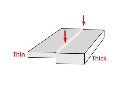
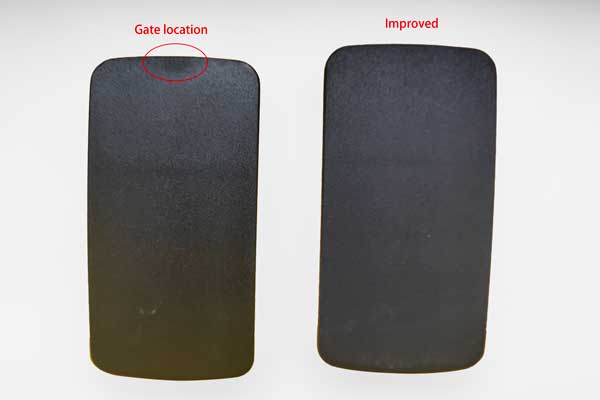
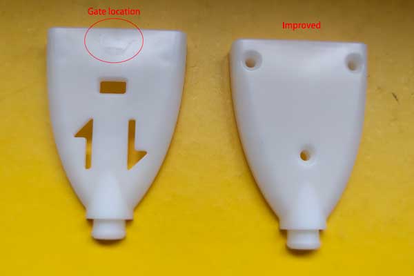
  • Improve Gate Design: Avoid gate designs in thick and open areas, and avoid the material from moving from thinner to thicker sections.
  • Segmented Injection Speed Adjustment: Slow down the injection speed when plastic enters more open areas to reduce snake flow marks.
  • Increase Mold and Nozzle Temperature: Higher temperatures for the mold and plastic improve flow and merging, reducing snake flow marks.
  • Enlarge Gate Size: A larger gate can improve molten plastic flow, thus minimizing snake flow marks.
  • Prevent Cold Material Entry into the Mold: For instance, adding a cold slug well to intercept cold material ensures only uniformly molten plastic enters the mold cavity.

In summary, these measures can effectively reduce the formation of snake flow marks in injection molding, enhancing product quality.

Conclusion on injection molding defects

These are the most common injection molding defects that we have dealt with in our earlier jobs. If you are the customer, you need to verify which flaws can not be accepted and be addressed beforehand so the injection molding manufacturer understands your quality requirements clearly. In order to avoid translation misunderstanding, when you work with overseas manufacturers, it will be better to use pictures to explain each defect.

Leave a Reply

Your email address will not be published.