Understanding Precision in Sheet Metal Fabrication
General Precision Requirements
Typically, sheet metal parts don’t require exceptionally high precision. The bending accuracy of these components can range between 0.25-1mm, which is sufficient for normal use. However, in some cases, higher precision may be necessary. It’s important to understand the achievable accuracy and the factors that influence it.
Key Factors Affecting Bending Accuracy
Machine and Tool Precision: The repeatability of the bending machine’s positioning and the precision of the dies are crucial. Different thicknesses and bend radii require specific dies for processing. Even slight changes in parameters can affect the dimensions of the bend.
Operator Expertise: Skilled operators play a vital role in adjusting the factors that impact bending accuracy. Proper force must be applied during the bending process, and the speed of the metal being fed must be carefully managed. High levels of concentration are required from operators, along with constant measurements and adjustments during the bending process.
Quality of Metal Sheets: The internal stress and uniform thickness of the metal sheets are significant. Inconsistencies in these areas can lead to poor dimensional consistency during bending.
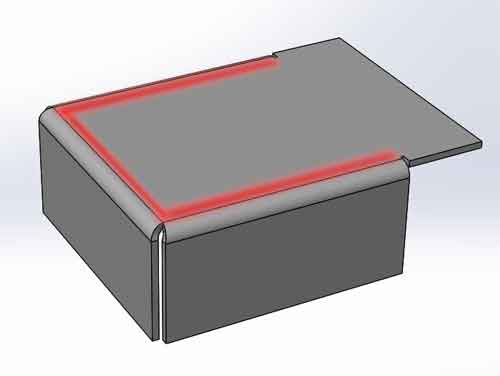
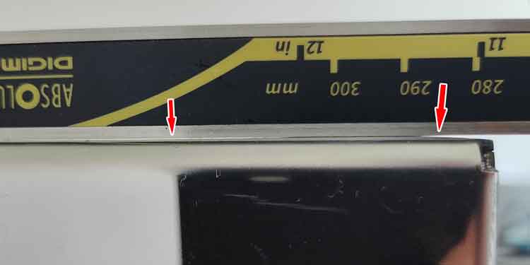
Flatness of Bent Parts: Although bent parts might appear flat, a straightedge or plane reveals that they are not perfectly flat. Bending causes slight bulging near the bend, and deformations are more pronounced where multiple bends intersect. Additionally, holes near the bend line can subtly influence local deformation.
(The red areas indicate the zones near the bends, which are more prone to bulging. At the intersection where bends cross, this bulging is even more pronounced.)
The photo reveals a wider gap near the bend on the right side, which corresponds to a greater bulge in that area.
Additionally, there are smaller gaps in the center, suggesting some irregularities there as well.
These gaps are not easily noticeable without using a straightedge for inspection.
Understanding these factors helps in managing the quality and efficiency of sheet metal fabrication, ensuring that the final products meet the required specifications and standards.
Comparing Sheet Metal Bending and CNC Machining
Reduced Precision Capabilities vs. CNC Machining
It’s important to note that sheet metal bending cannot achieve the precision of CNC machining. CNC machining typically deals with thicker metal parts, which lends these parts greater rigidity. This rigidity reduces the impact of random variables during the machining process, and precision largely depends on the accuracy of the machine itself.
Challenges with Sheet Metal
In contrast, sheet metal parts are usually thinner and their dimensions often require manual adjustments. These parts are more susceptible to various incidental factors that can affect their final shape and size.
Fabrication Processes
When using CNC machining, the part’s final shape directly corresponds to the 3D model used for programming.
Sheet metal fabrication, however, is not as straightforward. It involves empirical calculations, prototype processing, measurements, and adjustments to achieve the desired dimensions.
Tolerance Considerations
Due to these differences, when setting dimensional tolerances for sheet metal parts, it is advisable to allow a greater tolerance range. This accounts for the less predictable nature of sheet metal bending compared to the more controlled process of CNC machining.
Challenges in Measuring Sheet Metal Dimensions
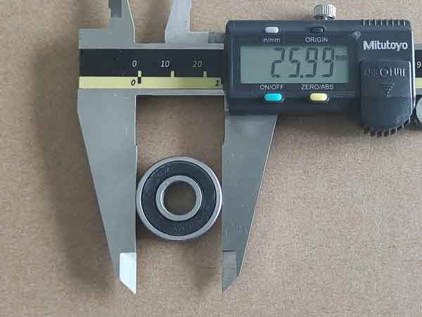
Measuring sheet metal parts accurately can be quite challenging. In comparison, when measuring bearings with a vernier caliper (which is often used for gauge calibration), it is relatively easy to achieve precise readings with variations only between 0.01-0.02mm.
Calibrating a caliper with a bearing is straightforward and allows for precise readings
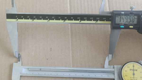
Using another caliper for calibration can be more challenging due to potential misalignment between the two calipers.
However, the same precision is hard to come by when measuring sheet metal parts. Repeated measurements of the same area can show significant variations, such as between 0.2-0.4mm. There are a few reasons for this:
Surface Irregularities and Deformations: As mentioned above, the surfaces of sheet metal parts can be uneven, especially near bends where deformations of about 0.1-0.2mm are common. Even a slight change in how the caliper is placed—either slightly in or out—can alter the readings.
Placement and Alignment Challenges: Unlike bearings, which have a regular cylindrical shape allowing the caliper jaws to fit snugly and align precisely with the diameter, sheet metal does not guarantee straightforward caliper placement. This misalignment can lead to reading inaccuracies.
The caliper jaw does not securely rest on the surface of sheet metal part near the bend
Implications for Measurement Practices
The fluctuation in measurements of sheet metal can be attributed to two main factors: the inherent unevenness of the part and inaccuracies in measurement technique. These factors often compound, leading to larger variations in the results.
To mitigate this, careful attention is needed during measurement, and it may be necessary to perform multiple measurements to obtain values that are as close as possible to the actual dimensions.
How to Ensure Precision in Sheet Metal Bending
Focusing on Critical Areas
Surface unevenness in bent sheet metal parts is common, but this doesn’t necessarily compromise the product’s functionality. Often, the tolerances for sheet metal components don’t need to be extremely strict; being within a reasonable range is typically sufficient for their intended use.
When sheet metal parts must fit together precisely in assemblies, it’s important to ensure dimensional accuracy in the specific areas required for fit, rather than over the entire surface. This targeted approach helps maintain functionality where it counts.
The illustrated section highlights a critical area with specific tolerance requirements, whereas the dimensional specifications for other areas are not as stringent.
Measurement Strategies
Using Fitting Parts or Gauges for Localized Measurement
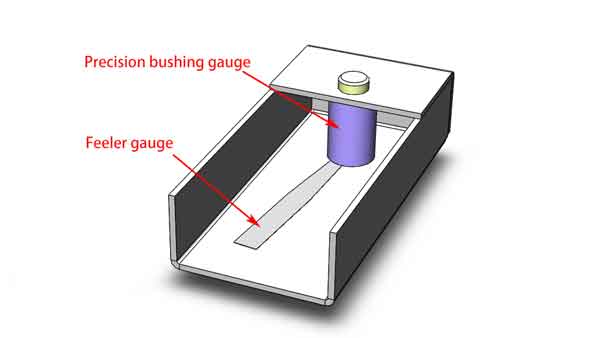
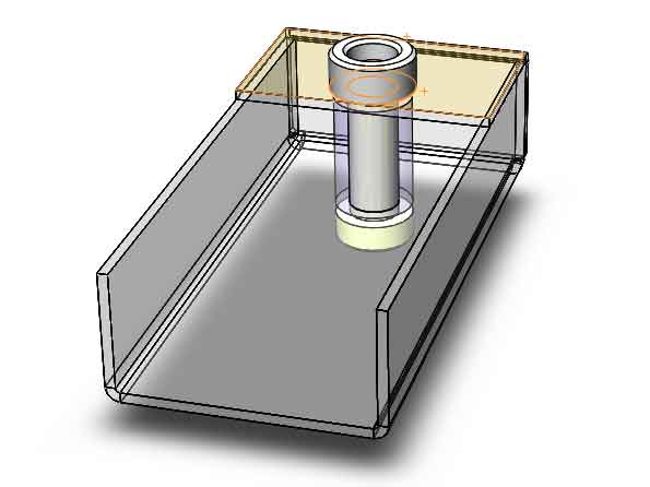
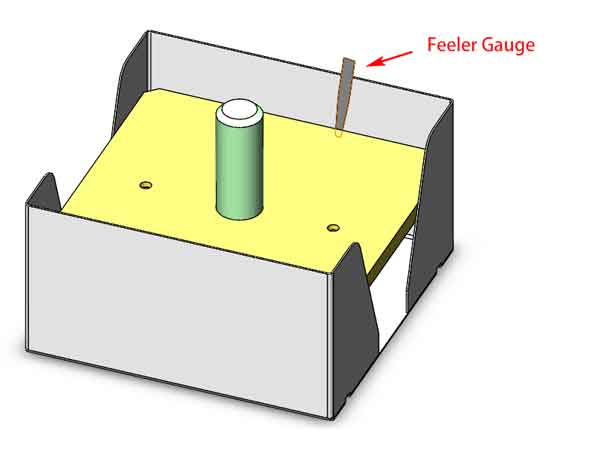
There are two main methods for measuring dimensions in localized areas. The first method involves using fitting parts, which generally provides a qualitative assessment. The second method uses specially made gauges that offer a quantitative measurement. For instance, in the given scenario, a feeler gauge can be used to check the gap after the gauge is inserted, revealing the precise dimensions required.
The purple object is a bushing designed with a specific height to work in conjunction with a feeler gauge for measuring internal dimensions.
Both methods are valuable depending on the needs of the assembly and the degree of precision required. By focusing on the critical areas of fit and using appropriate measuring tools, we can maintain the necessary precision in sheet metal bending projects.
Precision Through Design in Sheet Metal Bending
Enclosed Edge Bending for Accuracy
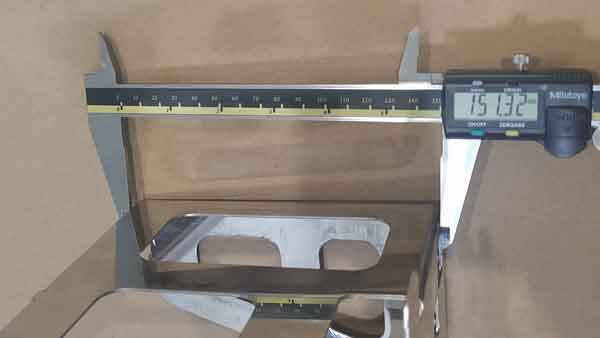
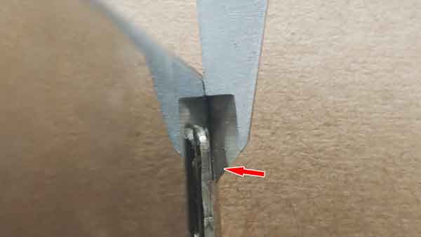
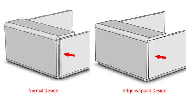
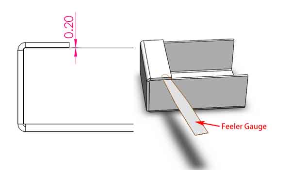
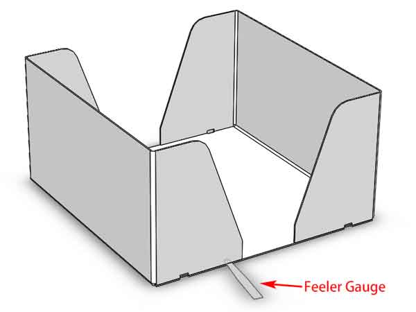
In an edge-wrapped design of sheet metal bending (see the right design on the below picture), the precision of the bend is crucial. For example, this particular design requires a gap of 0.2mm. To verify this, a feeler gauge can be used to measure the actual gap, which is a direct reflection of the bending precision. This method is typically more straightforward and accurate than using a vernier caliper.
In comparison: The component on the left uses a standard sheet metal bending design, while the one on the right features an edge-wrapped bending design.
The gap here can be checked with a feeler gauge to verify the precision of the bending.
Design Considerations and Manufacturing Tolerance
However, designing with such small gaps does carry the risk of a higher scrap rate. If the deviation exceeds 0.2mm, interference may prevent the parts from being bent fully to a 90-degree angle.. This tight tolerance compels manufacturers to adhere to higher precision standards in production, leaving no room for shortcuts.
When the gap at the bend is designed to be small, excessive dimensional deviations can prevent the bend from closing properly, potentially leading to the scrapping of the product.
Precision in sheet metal bending can be significantly enhanced by deliberate design choices, ensuring that components meet stringent requirements and fit together perfectly. While this does demand greater accuracy and care in the manufacturing process, the outcome is a more reliable and higher quality product.
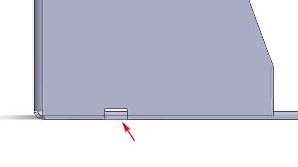
Using Notches for Quick Assessment of Bending Precision
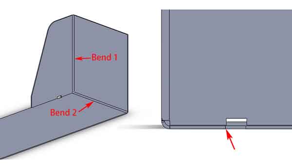
Adding a small notch here provides another method to assess bending precision quickly. By observing whether the notches align, we can gauge the accuracy of the bends. Of course, the degree of misalignment in these notches is determined by the cumulative error of the two bends (illustrated as the first bend and second bend). However, it offers a rapid way to observe and evaluate bending precision.
Theoretical perfect alignment of notch in sheet metal bending
The cumulative deviations from Bend 1 and Bend 2 can lead to the misalignment of the notch
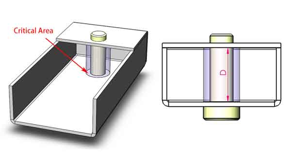
Utilizing Welding Fixtures for Dimensional Accuracy
When welding sheet metal components that require high precision, welding fixtures can be used to ensure accuracy. Take the sheet metal piece in the image as an example; it is designed to have a shaft mounted on it. For this assembly, it’s crucial that the two facing holes are perfectly aligned and the internal spacing dimensions are within tolerance. To achieve this, a welding fixture can be implemented to correct the dimensions to some extent during welding. However, it’s important to note that while the fixture can make minor adjustments, over-reliance on it can lead to warping or deformation of the product after welding. Therefore, ensuring bending precision is still of utmost importance.
A schematic diagram of a welding fixture
Assessing Bend Precision through Examples
Typical Precision in Sheet Metal Bending
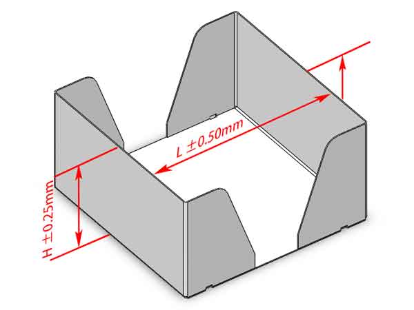
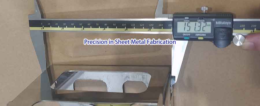
Let’s look at some examples to understand the precision that can be achieved in sheet metal bending. For a standard process, the bending height ‘H’ of this product can typically reach a precision of +/-0.25mm, and the post-bending length ‘L’ can achieve +/-0.5mm.
Typical bending precision of a sheet metal part
Gap Width Observations
However, as mentioned earlier, if we were to measure with a vernier caliper, we might find a variance of about 0.2-0.7mm, suggesting potential discrepancies beyond the acceptable range.
When examining the clearance with a feeler gauge, we generally find it falls between 0.05-0.25mm. Compared to the design target of 0.1mm, the maximum deviation observed is 0.15mm. This implies that directly measuring with a vernier caliper does not always yield precise results, and using the gap for assistance can provide more insightful results.
Evaluating Misalignment Through Slot Displacement
Assessing Slot Displacement
By closely examining the misalignment of this slot, measurements with a vernier caliper show a displacement ranging from 0 to 0.3mm. After evaluating three samples, we can infer that the cumulative error from misalignments on both sides would suggest that the ‘L’ dimension’s error falls within 0.1 to 0.5mm.
Importance of Aggregate Measurement
The collective misalignment on either side of the slot is a crucial aspect to consider for the overall dimensional accuracy of ‘L’. These findings underscore the importance of considering cumulative tolerances when assessing the precision of fabricated parts.
Utilizing Gauges for Internal Dimensions
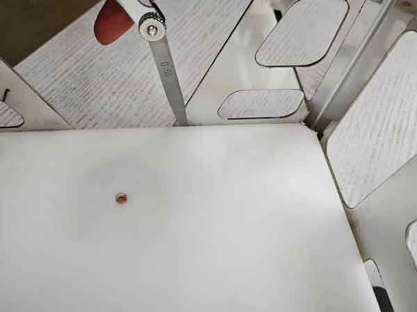
Furthermore, we used gauges to measure this part and found that when using a feeler gauge, the internal dimensions—Internal Length and Internal Width—were within the tolerance limits. This supports the point that vernier caliper measurements aren’t entirely reliable on their own. To ensure and verify bending precision, additional tools and methods should be employed.
Here, we employ the feeler gauge in conjunction with the inspection gauge to measure the internal dimension of this sheet metal component.
Conclusion
In conclusion, achieving precision in sheet metal fabrication is a balance of skill, appropriate tools, and knowledge. By understanding the measuring challenges and employing strategic techniques, fabricators can attain the high precision necessary for quality craftsmanship in this field.