Understanding and Applying Tolerances for Sheet Metal Bending Processes
Proper tolerancing for sheet metal bending jobs is important for making your designs ready for manufacturing. This post will briefly explain where the variations come from, and what the holdable tolerances could be for usual shop floor operations.
Where the variations come from
The bending (forming) process is a non-material-removal process.
In the material removal processes (like CNC machining), the machined geometry is mostly controlled by the precision of movements of the cutting tools. Other factors make much less contribution to the final precision of dimensions.
While in the bending of sheet metals, although the tools and dies can be made very precisely, the material elongation, springbacks, and grain direction, etc. all come into play. All these factors need to be taken into consideration for proper tolerancing of the sheet metal parts.
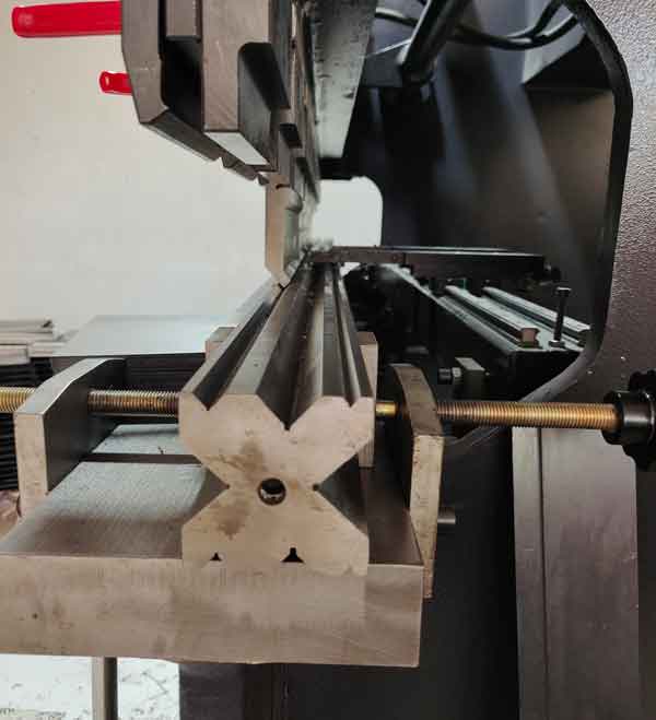
The bending process on a press brake
In reality, the thickness and tempered hardness of sheet metals will vary from sheet to sheet, or even on different areas within the same sheet.
Meanwhile, in the sheet metal bending process, the cut edge or formed edge are used as the datums for positioning the workpiece, these datums are less accurate than the CNC machined datums.
As a result, knowing the appropriate tolerances becomes very important. This will allow your sheet metal parts to be produced efficiently and at a low cost. Excess tolerance will drastically increase the checking and sorting works, and thus increase the prices and lower the production speed.
punch, die and back gauge for a press brake
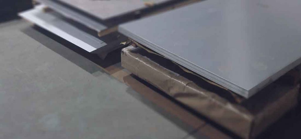
Material thickness variations
In real life, the sheet metal thickness may vary a little bit in its allowed variations. For example:
2mm cold-rolled steel: 1.90-1.97mm
5mm hot-rolled steel: 4.60-4.80mm for branded; 4.40-4.75mm for non-branded (poorer quality and cheaper)
The thickness variations have a major impact on the precision of finished parts.
Two types of variations for sheet metal bending
1. Angular
When the punch (the upper die) is released, the part will flex back a little. The amount of springbacks will not be consistent all the time, it is affected by the material hardness and thickness.
If the bending radius and material hardness is chosen correctly, the bend angle can normally be made to +/-0.5° to +/-1°
springback of bending
How it affects the linear dimensions
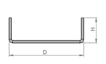
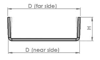
When we are taking measurements of the linear dimensions, we should measure the near side of the bends, because the measurements on the far side are less accurate and consistent (see the pictures below).
Ideal
In reality
2. Linear
In the bending process, the bent area is stretched thinner and becomes longer (elongated). Again, the amount of elongation is not consistent due to unevenness of material thickness and harness, which caused the inconsistency of dimensions.
Controlled vs uncontrolled dimensions
The linear dimensions can be classified as controlled and uncontrolled dimensions.
The controlled dimensions are directly derived from the bending by placing the flat sheet against the back gauge, thus they are under a better control.
The uncontrolled dimensions are indirectly obtained from 2 or more bends, they should be given larger tolerances.
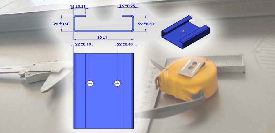
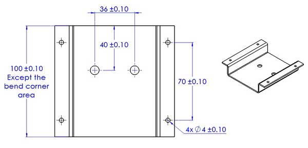
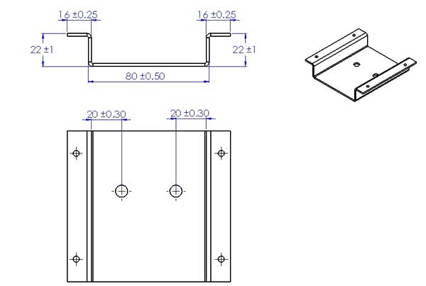
An example
Assuming we are going to produce a part like this, and it will go through 2 steps
First step
Second step
The controlled dimensions can be held to a tighter tolerance than the uncontrolled dimensions, as shown below:
Normal tolerances for sheet metal bending
In real practices, the holdable tolerances will vary by many factors, like material thickness, overall span of dimensions, cold-rolled steel or hot-rolled steel, and so forth. A quicker and easier way is to look at some examples to get some ideas, then work with your DFM engineer for the proper tolerancing of each specific job.
Condition on the below examples: the material thickness is less than 2mm, the parts are made by laser cutting and press brakebending.
These examples give the “comfort zones” of tolerances, but they are only for large volume production when the tools, material, and processes have been optimized. For small runs of production, the tolerances may still need to be loosened up.
Laser-cut dimensions: ±0.10 to ±0.20mm (more accurate)
The laser-cut dimensions include hole diameter, hole to hole distance, hole to edge distance, length and width of the blank, and so forth. For large spans (like 2 meters), the tolerance may increase to ±1mm.
Bent dimensions: ±0.25 to ±2mm (less accurate)
The bent dimensions include hole to bend, bend to edge, and bend to bend.
The tolerances will vary depending on the bending sequence. The first bends will be more accurate, it uses the cut edge as the datum, the next bends using bent edge as datum will be less accurate. The last uncontrolled dimension will be the least accurate.
Using the cut edge as the datum plane
More accurate
Using the bent edge as the datum plane
Less accurate
Tip: You will find out it is difficult to hold the hole (or other features) to bend or hole to hole (after bending) distances to a tight tolerance. When tight tolerances for these are inevitable, these holes (or other similar features) should be CNC machined after bending.
Prioritize the tolerances
If we take different bending sequences, we can get different tolerances on each dimension. That is why it is important to instruct which are the key dimensions, or explain to your manufacturer how the parts function in their assembly.
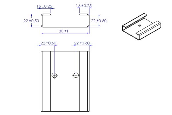
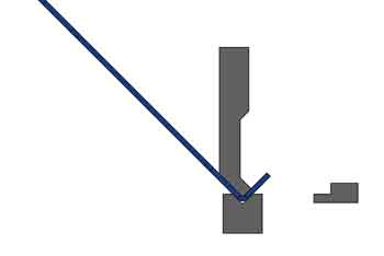
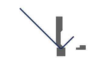
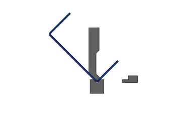
Bending sequence 1
Step 1
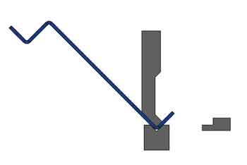
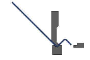
Step 3
Step 2
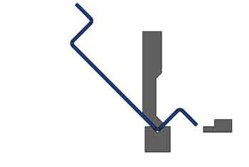
step 4
With this bending sequence, the bottom width is 80±1mm, while the height is 22 ±0.50mm.
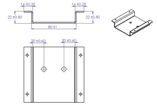
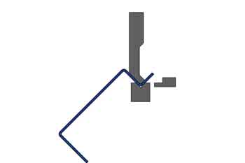
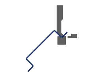
Bending sequence 2
Step 1
Step 3
Step 2
Step 4
This is an unnormal bending sequence, special tools are required to avoid the workpiece interfere with the machine.
With this bending sequence, the bottom width can be held to 80±0.5 mm, but the height can only be made to 22 ±1 mm.
Conclusion
This post is to help you understand what the holdable tolerance can be for your sheet metal parts. However even for an experienced designer, it may be difficult and time-consuming to decide the tolerances for each and every dimension, an easier approach is to explain to the manufacturer or DFM engineer how the part fits and functions in the assembly, how it interacts with the mating components. They have the experience or may make some inspection fixtures based on your information, and work out the most suitable tolerances for the key dimensions.
Boyan Manufacturing Solutions has rich experience in sheet metal fabrication. If you have any questions, please leave a message below, or send your drawings for consultation.