Draft Angle: A Vital Element in Plastic Injection Molded Product Design
Much like wall thickness, the draft angle plays a crucial role in the design of plastic injection molded products—a facet that demands attention from product designers. Neglecting the draft angle in the initial stages of product design, and deferring it entirely to the mold engineer for subsequent adjustments, can significantly amplify the workload and development cycle. This article aims to provide a concise introduction to the fundamental concepts of plastic product draft angles.
Table of Contents
ToggleUnderstanding Draft Angle in Injection Molding
What is Draft Angle?
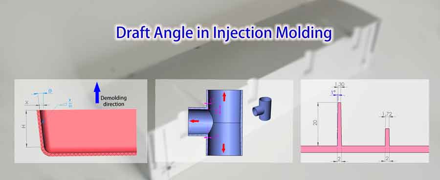
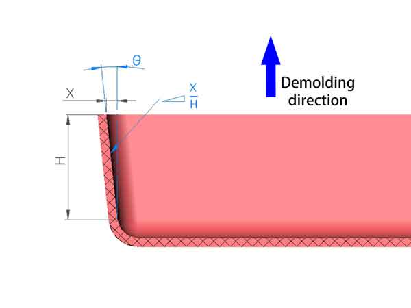
Draft angle is a critical element in the world of injection molding. It refers to the inclination angle set on the side wall of a plastic product in the demolding direction, which plays a pivotal role in the smooth demolding of the injection molded product. To put it simply, it’s the angle that facilitates the easy removal of the product from the mold.
Expressing Draft Angle
There are two common ways to describe the draft angle. One way is to measure it in terms of angles, which usually varies from 0.5° to 2.0°. Alternatively, it can also be described using the ratio of the indentation’s depth (X) to its height (H). While the angle measurement is more widely used, the second method offers a clearer picture of the side wall’s indentation.
The Importance of Draft Angle in Injection Molding
Why is a Draft Angle Necessary?
During the process of injection molding, products tend to shrink as they solidify and cool inside the mold cavity. This shrinkage leads to a tight fit between the side walls of the plastic product and the corresponding walls of the mold. Consequently, a significant amount of resistance (frictional resistance) is generated during the demolding process.
By incorporating a draft angle, a small gap is created between the product and the mold when the product is partially separated from the mold. This minute gap allows for a smoother and more effortless separation, effectively minimizing or even eliminating the demolding resistance (frictional resistance). The inclusion of a draft angle is thus indispensable in ensuring the seamless and efficient demolding of injection-molded products.
Consequences of Inadequate Draft Angle
Inadequate draft angles can lead to several critical issues, including:
Scratches on Plastic Product Side Walls: When the draft angle is insufficient, it can result in the unwanted friction and scraping of the plastic product against the mold’s walls. This can lead to unsightly scratches on the side walls of the plastic product, compromising its overall quality and appearance.
Surface Damage and Integrity Compromises: The lack of an appropriate draft angle can cause severe damage to the surface and structural integrity of the plastic product. This damage may manifest as whitening of the plastic, deformation, or even localized damage in certain areas. These defects not only affect the aesthetics but also the functionality of the product.
Accelerated Mold Wear and Reduced Lifespan: Inadequate draft angles impose additional stress on the mold. As a result, the mold’s wear and tear increase significantly, causing it to deteriorate at a faster rate. The lifespan of the mold shortens, leading to the need for more frequent replacements or repairs, which can be costly and disrupt production efficiency. Proper draft angles help mitigate this issue, prolonging the mold’s lifespan and reducing maintenance costs.
Types of Draft Angle and Design Guidelines
1. Outside walls:
For polished surfaces, it’s generally recommended to have a draft angle of 1-1.5°. If the surface quality demands are high, opting for a 1.5° angle is safer to prevent surface scratching.
For walls not very tall, a draft angle of 0.5° can be used if necessary, but it’s crucial to properly position the ejector pins to ensure the product can be smoothly ejected.
For outer surfaces with textures, the corresponding draft angles are listed in the table below.
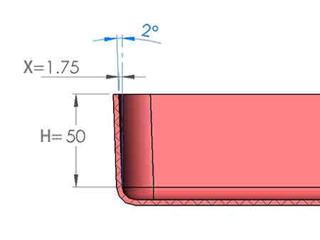

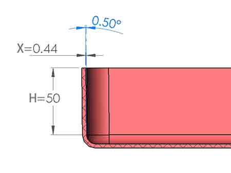
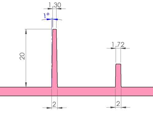
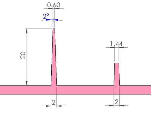
These 3 images show how much the indentation of the side wall is when the draft angle is 0.5°, 1°, and 2°.
Tip: Preventing Sticking to the Upper Mold:
In the case of a two-plate mold where the upper mold lacks an ejection mechanism, it is crucial to prevent the product from sticking to the upper mold during the mold-opening process. Failure to do so may necessitate manual intervention using tools to remove the part from the mold.
Frequent occurrences of this issue can disrupt smooth production and potentially affect the mold’s functionality. Consequently, the lower mold is often designed as a convex mold, ensuring that the plastic product adheres more tightly to it after shrinkage and is more likely to separate from the concave mold.
2. Reinforcing Ribs:
Similarly, a draft angle of 1-1.5° is suitable for them. However, if there is a large number of ribs and they are tall, a slightly larger value should be selected to prevent challenges during product ejection. On the other hand, if the number of ribs is small and their height is low, a smaller draft angle, such as 0.5°, can be chosen.
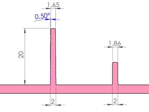
Due to the draft angle, the top of the ribs will be slimmer than the bottom. The impact of using different draft angles on the top thickness can be illustrated with three images below.
Height of the Ribs
Generally, it’s recommended for the height of the ribs to be less than 3 times the wall thickness. This guideline is not absolute; ribs can sometimes be taller, but this requires careful selection and control of the draft angle size.
However, the taller the ribs, the deeper the corresponding slots in the mold, increasing the mold machining costs and the difficulty of ejecting the product.
Thickness of the Ribs
To avoid noticeable sink marks on the outer walls, the recommended thickness for the ribs is less than 0.6 times the thickness of the outer wall, with a preference for even less than 0.5 times to further minimize sink marks.
However, if achieving this is challenging, it might necessitate compromising the appearance of the product. After all, some sink marks on the product surface are acceptable in certain scenarios.
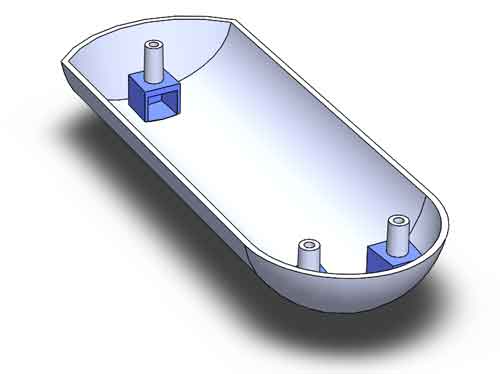
Bosses
For bosses, due to the presence of an ejector tube, larger ejection forces can be applied, allowing for a reduction in the draft angle to 0.5-1°.
Blind Holes vs. Through Holes
In the case of blind holes, since the angle of inclination is opposite to that of the outer walls, the wall thickness at the top will be noticeably less than at the bottom. To avoid sink marks at the bottom, it is recommended that the bottom wall thickness of the boss be less than 0.6 times the thickness of the outer wall.
With through holes, since both the hole and the outer walls can be inclined in the same direction, the wall thickness can remain relatively uniform throughout the height. Additionally, since the core of a through hole is supported at both ends, it allows the boss to be made taller. Thus, for taller bosses, it is advisable to use through holes.
A tip to avoid sink marks beneath the boss
Another solution is to add a void structure underneath the boss, akin to building a small house to support the boss. This can ensure a sufficient wall thickness for the boss without causing sink marks, but it requires an additional sliding mechanism and ensures gate design with efficient filling, thereby the cost will be increased.
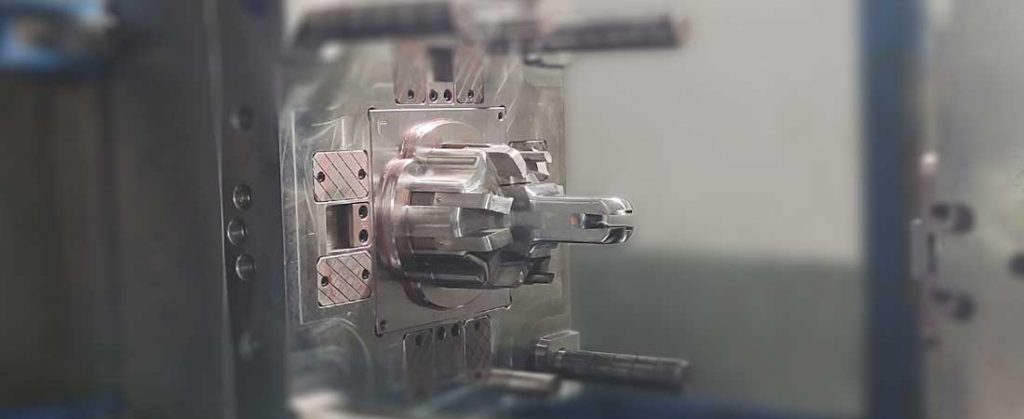
4. Sliders:
Draft angles along the direction of the slider’s extraction are essential for facilitating the smooth movement of sliders during the injection molding process.
Draft angles in the direction of the slider’s extraction are crucial to ensure the smooth withdrawal of sliders. Similarly, a general range of 0.5-1.5° for draft angles is recommended, but this should be assessed on a case-by-case basis.
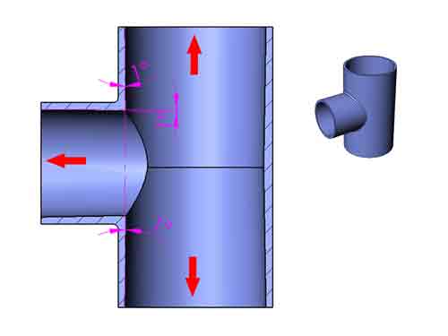
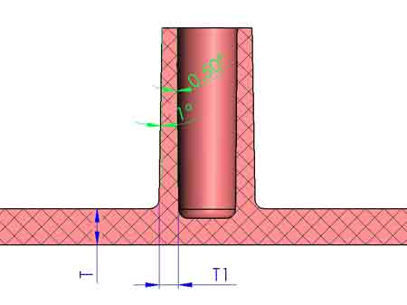
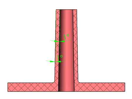
Note: In the illustrated example, the T pipe’s outer diameter is formed through upper and lower mold clamping without axial extraction. As a result, no draft angle is required for the outer diameter.
However, for the inner holes crafted with three inserts, a 1° draft angle is incorporated in the direction of extraction.
As a product designer, you only need to focus on general draft angle principles. Reach out for assistance; we’re here to help you check and refine draft angles.
Key Factors Influencing Minimum Draft Angle
Several critical factors impact the determination of the minimum draft angle required for successful demolding in injection molding. These factors include:
1. Surface roughness: Sometimes, different textures need to be applied to the surface of plastic parts. The surface roughness of these textures will determine the corresponding minimum draft angle, which we’ll discuss in the next section.
2. Shrinkage: Products with significant shrinkage necessitate a larger draft angle to facilitate mold extraction from the plastic part.
3. Wall Thickness: Increased wall thickness results in greater wrapping force on the mold, thereby demanding a larger draft angle for effective demolding.
4. Frictional Resistance: Higher levels of frictional resistance call for the utilization of a larger draft angle to ensure smooth and efficient demolding.
5. Complexity of Design Features: The presence of multiple reinforcement ribs, holes, and bosses in the design amplifies the required extraction force, compelling an appropriate increase in the draft slope to ensure successful demolding.
Correlation between Surface Texture and Draft Angle
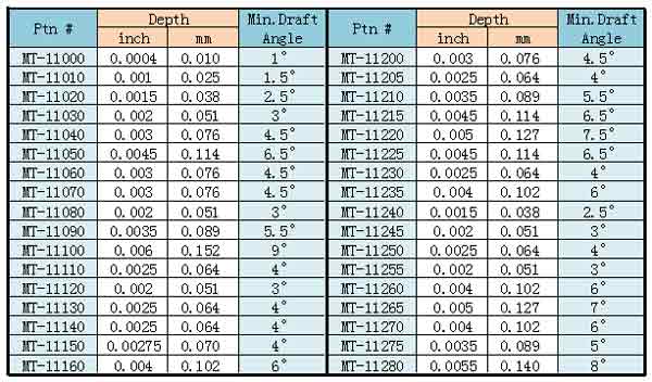
An influential factor in determining the minimum required draft angle is surface roughness. It’s essential to recognize that when creating surface textures, the depth of the texture directly influences the necessary draft angle. Deeper textures, indicating higher surface roughness, demand a greater draft angle to prevent surface strain during mold ejection.
This table outlines the minimum draft angle required for different surface textures, serving as a guide for optimizing the draft angle based on the intricacy of the surface finish.
Utilizing Collapsible Cores to Eliminate Draft Angles
Introduction to Collapsible Core Technology
Although draft angles are acceptable in most cases, there are scenarios where a zero draft angle is desired. This can be achieved using a structure known as a collapsible core. Composed of several parts, this core’s components move vertically relative to each other during demolding, which translates into a horizontal reduction in the core’s size.
Illustration of How Collapsible Core Works
Collapsible cores come in various designs, some that contract entirely around the circumference and others that only contract in one direction. The latter has fewer parts and is less costly. Due to its simpler structure, we will explain its working principle with an illustration below.
The following is a 3D diagram showing two sliders connected to a central middle piece via dovetail slots. When the mold opens, the sliders move upward relative to the middle piece, shortening the distance between the sides and creating a gap between the mold core and the product.
Below is a two-dimensional cross-sectional view that displays the change in dimensions.
With this structure, it’s possible to create plastic products with a zero draft angle or even a negative draft angle, where the inner walls are inclined inward.
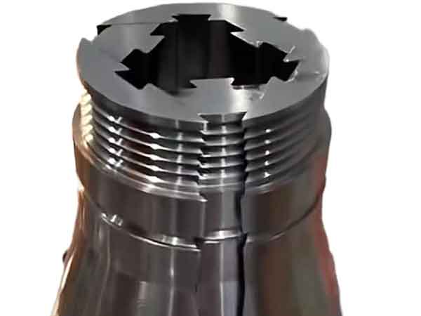
6-Segment Collapsible Core
However, the more common collapsible core structure consists of 6 segments and is used for circular internal cavities.
As you can see, this six-segment collapsible core structure can be used to create internal threads in plastic components without the need for an unscrewing motor.
Conclusion
In conclusion, understanding the pivotal role of draft angles in plastic injection molding is key for efficient product design. By acknowledging its impact early on, designers can enhance collaboration and streamline the development process, ensuring optimal results in the intricate realm of injection molding.