The Importance of Injection Mold Assembly and Manual Fitting
In the injection molding manufacturing process, mold assembly and manual fitting are crucial stages that require considerable time and effort. These processes demand meticulous attention to detail, a wealth of experience, and precision craftsmanship.
A careful and deliberate approach is essential to achieving optimal mold quality. Only through this level of precision can a high-quality mold be ensured.
What is Manual Fitting?
Manual fitting refers to the process of adjusting the dimensional accuracy of individual mold components by hand after they have been machined. This ensures that all mold componentsfit together perfectly, align correctly, and achieve the necessary clearances for moving components such as sliders, lifters, and ejector pins. The aim is to fine-tune these components for precise function and alignment during the injection process.
Key Areas to Inspect in Manual Fitting
When performing manual fitting, several critical areas require inspection:
1. Parting Surface: The parting surface of the mold must be flat and well-aligned. Poor contact or gaps between these surfaces can result in flash during injection molding. Achieving perfect alignment is relatively straightforward for flat surfaces, but can be more complex for three-dimensional parting lines.
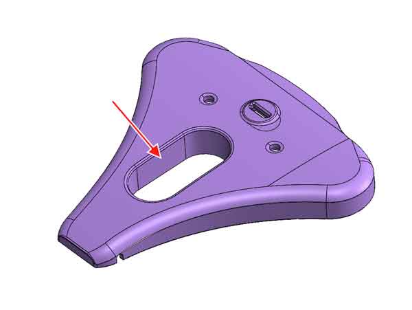
2. Punch-Through Surface: The punch-through surfaces, which create openings in the molded part, must fit precisely.
a plastic component with an opening
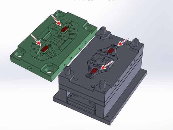
The mold core and cavity need to contact each other at the correct height to ensure uniform contact when the mold closes. Misalignment here can lead to uneven pressure and flash formation.
The punch-through surface in a 3D view
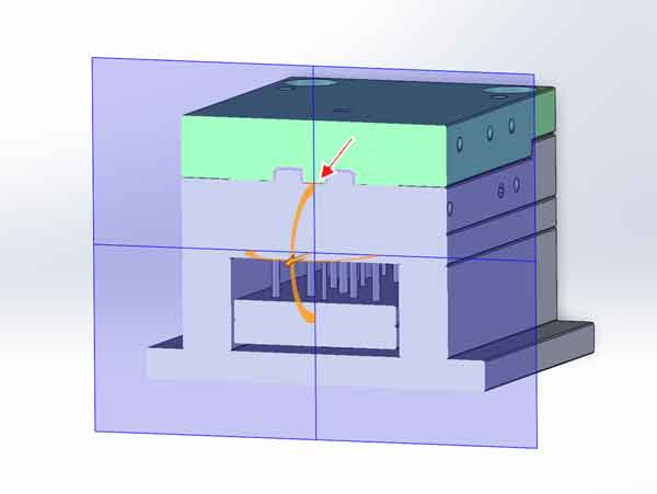
The punch-surface in the cross-sectional view.
3. Sliders and Lifters: Sliders and lifters must have the correct clearance with their guide rails, typically between 0.01 and 0.05 mm, depending on size. These components also need to be flush with the mold core to avoid mismatch lines or dimensional issues on the molded part.
4. Sharp Edges and Burrs: While chamfering during CNC machining can be costly, it is common practice to manually remove burrs and sharp edges using grinders to ensure smooth operation and avoid damage during mold assembly.
5. Mold Venting: Proper venting is essential to allow air to escape during injection molding. Vents must be checked to ensure they are of the correct size. Oversized vents can lead to flash, while undersized vents may trap air and cause defects.
By focusing on these areas during manual fitting, mold makers can ensure the smooth operation of the injection mold and prevent defects during production.
Common Inspection Methods
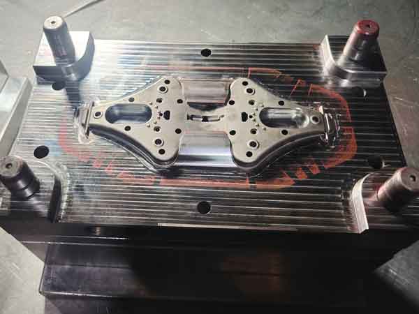
The most commonly used method for checking the fit and alignment of machined mold surfaces is the use of red or blue marking compound (referred to as “Red Dan” or “Blue Dan”). This technique is often complemented by precise measuring tools such as vernier calipers and micrometers.
Note: Red Dan: It has a harder texture and is relatively rougher, making it more suitable for large-area mold fitting or alignment of heavy mechanical parts. It can show more pronounced contact points. Blue Dan: It has a softer texture and is ideal for precise mold fitting, clearly displaying lighter contact marks. It is suitable for high-precision mold alignment checks.
With the continuous advancements in machining and measuring technology, the use of coordinate measuring machines (CMM) has become increasingly popular. CMMs can provide a complete profile of the part being measured and can often replace the traditional Red Dan method for more accurate and comprehensive inspections.
Red Dan Inspection Method
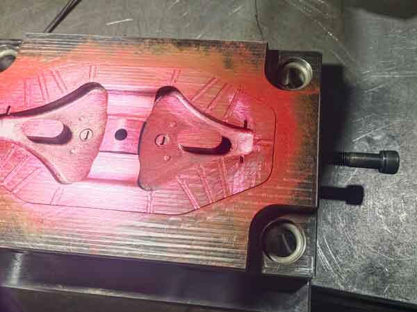
The Red Dan (or Blue Dan) method involves applying a thin, even layer of marking compound onto one half of the mold surface. It’s important to ensure that the application is uniform and of consistent thickness.
The two halves of the mold are then brought together and pressed firmly to ensure full contact.
After separating the mold halves, the transfer of Red Dan onto the opposing mold surface is inspected.
Good Fit: If the surfaces are well-aligned, the Red Dan will transfer evenly to the corresponding surface of the other mold half, indicating an even and proper fit.
Too Tight Fit: A deep color indicates minimal clearance between surfaces, suggesting a very tight fit.
Large Gaps: A lighter or uneven color suggests larger gaps between the surfaces. If no Red Dan is transferred, this indicates significant misalignment, and the areas in question will require further adjustment in dimension or shape.
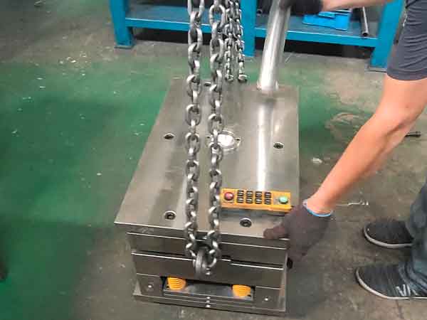
Once the mold halves are brought together, it’s important to use a copper or aluminum rod to hammer the mold with force to ensure a tight contact of the mold halves. Failure to do this could result in large areas without any Red Dan transfer, leading to incomplete inspection and inaccurate results.
Tapping the mold with an aluminum rod to transfer the dye.
For improved efficiency, the use of a mold spotting press is highly recommended. This machine can apply uniform pressure across the mold surfaces, achieving a better transfer of the marking compound than manual hammering. Additionally, it reduces the physical strain on workers and speeds up the process. For larger molds, using a clamping machine is essential, as their weight makes manual handling impractical and ineffective for achieving accurate results.
Adjustment Methods
There are several methods for adjusting the dimensions of injection mold components to achieve the necessary precision:
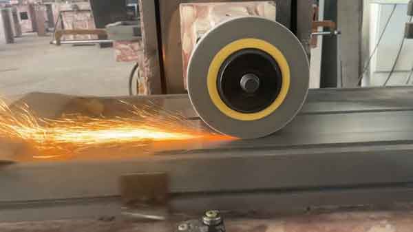
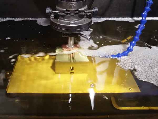
1. Grinding Machine
One of the most commonly used methods for adjusting the height of flat surfaces is the grinding machine. This approach is fast, convenient, and cost-effective, making it ideal for minor adjustments to the planar sections of mold parts.
2. Manual Fine-Tuning
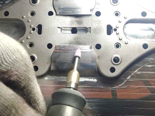
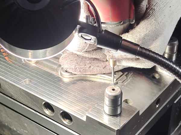
For curved surfaces, manual adjustments are typically limited to small, localized corrections. Tools such as files, sandpaper, and electric grinders (like rotary tools or angle grinder) are used to refine specific areas. This method is often done gradually, using the previously mentioned Red Dan technique to get closer to the desired dimensions. However, because manual fine-tuning is time-consuming, it’s best suited for minor adjustments rather than large-scale changes.
Use a rotary tool to remove excess material and adjust the size.
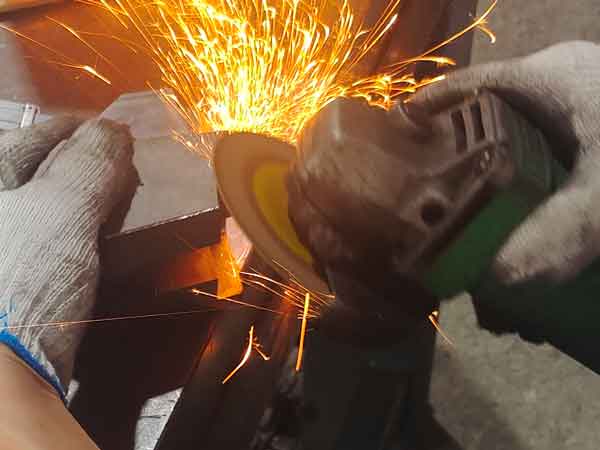
Use an angle grinder to chamfer sharp edges
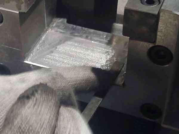
Use a file to grind off excess material and adjust the size.
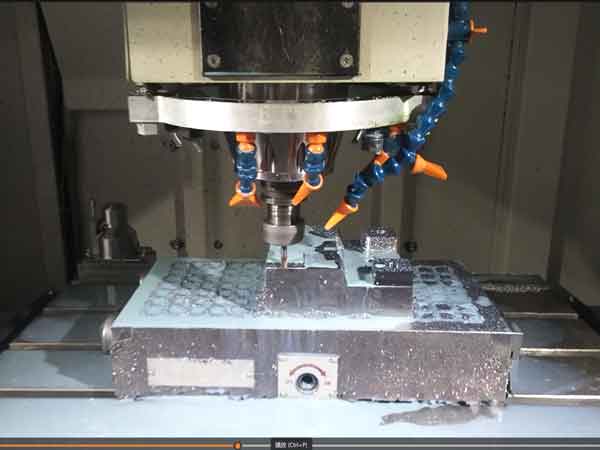
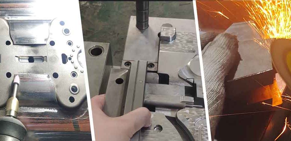
3. CNC Milling and EDM Reworking
When larger adjustments are required, particularly for complex contours or surfaces with significant deviations, CNC milling machines or electrical discharge machining (EDM) are needed to rework the part. Manual corrections are not precise enough for major modifications, especially in molds with high dimensional accuracy requirements. Additionally, manual filing is discouraged in high-precision molds where visible tool marks are unacceptable and can compromise the quality and functionality of the final product.
CNC milling
EDM (Electrical Discharge Machining)
These methods ensure that mold parts can be adjusted efficiently while maintaining the high levels of accuracy needed for optimal mold performance. Each method has its specific use case, with manual methods suited for minor touch-ups and more advanced machining required for significant corrections.
Inspection of Sliders and Lifters
During the manual fitting process, the inspection and adjustment of sliders and lifters are significant tasks. Ensuring their dimensional and geometrical accuracy, as well as maintaining proper clearance with their guide rails, is critical.
Inadequate fitting can affect the accuracy of the plastic parts being produced and accelerate the wear of these components during mold operation.
Tactile Inspection
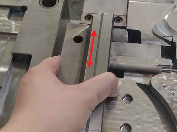
One commonly used method to assess the fit and clearance of sliders and lifters is through tactile inspection. This involves manually moving the sliders (and lifters):
Lateral Movement: When moving the slider side-to-side, there should be no noticeable play or looseness.
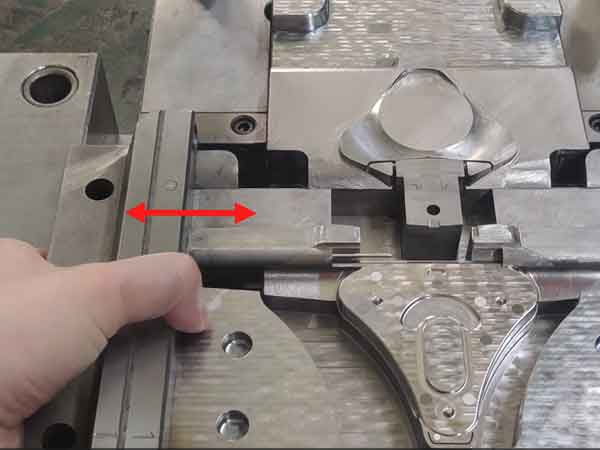
Forward and Backward Movement: The slider should move with the right amount of resistance—neither too tight nor too loose.
If the fit is too tight or the component does not fit at all, material can be removed to reduce the dimensions slightly. However, if the fit is too loose, the only solution is to remake the slider or lifter to achieve the correct size and tolerance. Therefore, great care must be taken during the adjustment process to avoid excessive removal of material.
Given the precision required for fitting sliders and lifters, this process demands experienced technicians with strong skills. The accuracy and efficiency of manual mold fitting rely heavily on their expertise to ensure that all components are aligned and function as intended.
Mold Fitting Timeline
The process of manually adjusting mold dimensions for precision is labor-intensive and time-consuming, which is why it constitutes a significant portion of the overall mold manufacturing cycle.
Simple Products: For products that only require fitting flat parting surfaces, the process is relatively quick, usually taking around 1–2 days.
Punch Through Surfaces: If the mold includes punch-through surfaces, the fitting process becomes more complex and typically takes 2–3 days to complete.
Sliders and Lifters: When a mold has numerous sliders and lifters, the time required increases significantly. Depending on the number and complexity of these components, the fitting process can take anywhere from 3 to 10 days.
In summary, the mold fitting timeline largely depends on the quantity and complexity of sliders and lifters involved. The overall size of the mold and its structural complexity also play a role in determining how long the fitting process will take.
Summary
In conclusion, mold assembly and fitting are vital stages in the overall injection mold manufacturing process. They significantly influence the duration of the manufacturing cycle and are crucial for ensuring the quality of the molds.
Should you have any questions, feel free to contact us or leave a comment below, and we will do our best to provide answers.