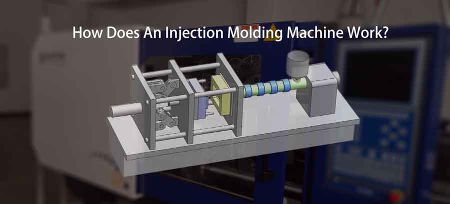
How an Injection Molding Machine Works: Unveiling the Process
The basic principle of how an injection molding machine works is to heat plastic particles to a molten state, injecting them into a mold cavity for subsequent cooling and shaping. This fundamental process is remarkably straightforward.
Remarkably, even miniature manual injection molding machines are available for home garage use, capable of crafting small batches of plastic products.
In contrast, professional-grade injection molding machines feature substantial tonnage, facilitating the production of sizable plastic items or products with multiple cavities. These advanced machines boast precision control and streamlined automation, enabling large-scale, high-quality manufacturing.
Injection molding machines come in various types, and for illustrative purposes, we’ll focus on the working principles of a horizontal reciprocating screw injection molding machine.
Table of Contents
ToggleUnderstanding the Screw’s Structure and Function in Injection Molding Machine
The screw within an injection molding machine stands as a remarkable invention, having evolved through a distinct process to become the widely used structure it is today. It serves two fundamental functions:
Injection Function:
Think of it as a giant syringe – the screw, acting as a plunger, plays a pivotal role in pushing the molten plastic into the mold cavity with substantial pressure. This forward motion is powered by the cylinder situated at the rear of the machine, generating the high injection pressure required for the process.
Material Feeding Function:
As plastic raw materials are consumed with each injection, a constant replenishment is necessary. The screw comes to the rescue here by continuously advancing material forward through its spiral blades via its own rotation.
It’s important to note that while this rotational movement facilitates material feeding, it cannot replace the pressure generated by the reciprocating motion of the screw.
This innovative design allows the injection molding machine screw to simultaneously serve these vital roles, making it a pivotal element in the injection molding process.
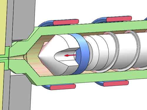
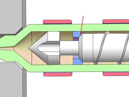
Check valve on the screw head
There is a check valve at the head of the screw. Its function is to prevent the reverse flow of melted plastic when the screw is advanced, while at the same time allowing the material to flow forward during feeding. It is implemented by checking ring. The checking ring has a distance of free movement forward and backward at the reduced step of the screw.
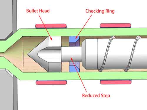
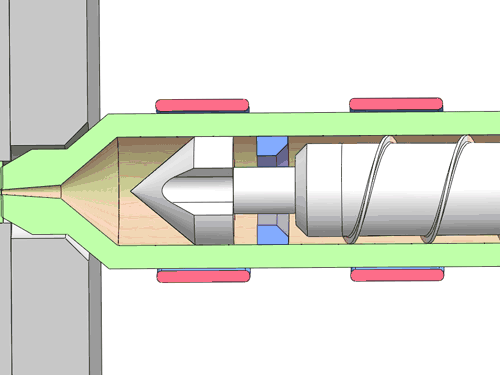
When the checking ring moves forward against the flat surface of the front cone, there are several slots that allow the material to flow forward, and when the checking ring moves backward against the rear conical surface, they form a sealing surface that blocks the material reflux.
Squeezing and Plasticization of the Screw
If you examine the screw closely, you’ll notice that the diameter of its middle section gradually increases from the rear to the front. This design results in the continuous reduction of the chamber’s volume situated between the two spiral blades.
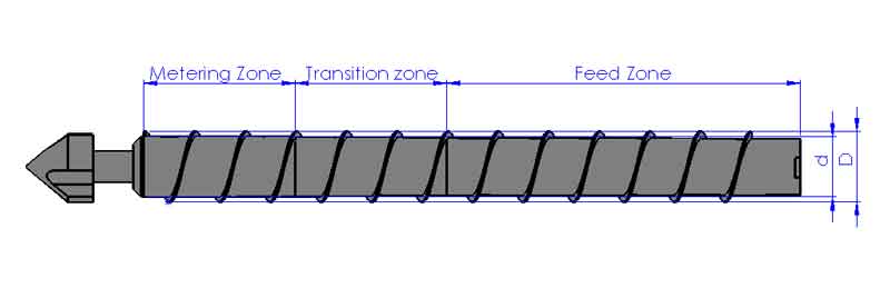
The screw’s length can be divided into three distinct zones: the feed zone, the transition zone, and the metering zone. Throughout each of these zones, the chamber volume undergoes a gradual reduction, with the transition zone at the center experiencing the most pronounced change.
In this way, when the plastic particles are transported from the tail to the head of the screw, they will be continuously squeezed and the temperature will rise. At the same time, they will be stirred. Under the simultaneous heating of the external heat band, they will reach a melting state, thereby achieving the effect of uniform plasticization.
The Fundamental Structure of an Injection Molding Machine
Now we already know the essential of the central component – the injection molding machine screw. This understanding will serve as a solid foundation for comprehending the machine’s holistic design. Now let’s explore the injection molding machine in more detail.
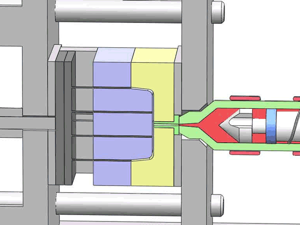
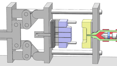
The injection molding machine can be divided into three distinct sections: the injection unit, mold assembly, and clamping unit. Let’s delve into each of these sections for a comprehensive overview.
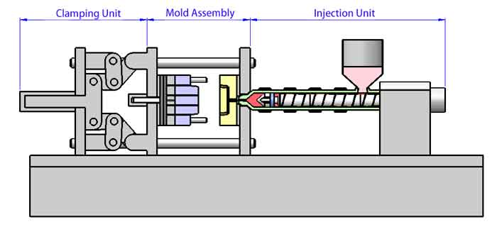
The Injection Unit
Within the injection molding machine, the injection unit plays a pivotal role in shaping the manufacturing process. Let’s explore its key components and functions in detail:
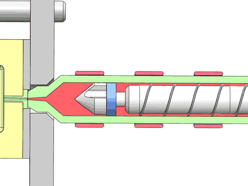
Screw and Barrel
As previously introduced, the screw and barrel form the core of the injection unit, responsible for melting and pushing the plastic material into the mold.
Hopper
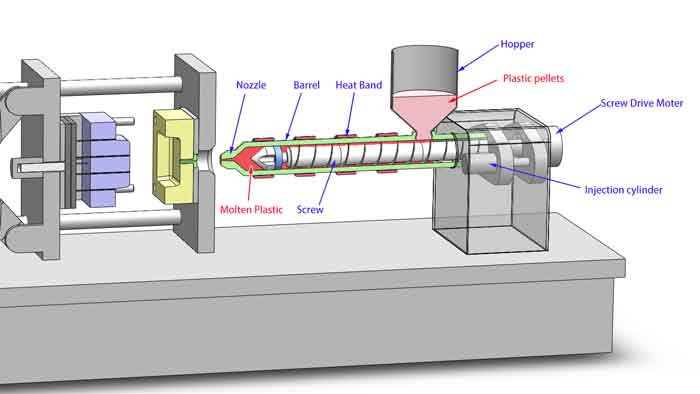
This crucial component is tasked with supplying plastic pellets into the barrel. Additionally, it incorporates a heating device to maintain the plastic particles at an elevated temperature and ensure they remain dry. This is especially important for many plastic raw materials, as moisture must be removed during the injection molding process.
Driving Device
The driving device comprises several essential elements:
- Screw Drive Motor: This motor powers the rotation of the screw.
- Injection Cylinder: It facilitates the forward movement of the screw, applying the necessary injection pressure.
- Injection Seat Cylinder: This cylinder enables the entire injection seat to move forward and backward, allowing the nozzle to make contact with and detach from the mold
Injection Volume
An integral parameter for measuring the screw’s capabilities, injection volume refers to the weight of plastic material that can be injected in a single shot. This measurement is typically expressed in grams. It’s essential to ensure that the total weight of plastic products produced in a single injection shot does not exceed the injection volume capacity of the injection molding machine. This ensures the machine operates within its specified limits and yields high-quality results.
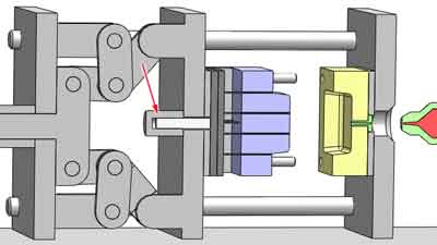
The Mold Assembly
The mold assembly, a critical part of the injection molding machine, has been introduced in detail in another article available on our website. However, it’s worth noting some additional components and functions within the mold assembly for a more comprehensive understanding:
Ejector Cylinder
Positioned at the rear, the ejector cylinder plays a crucial role in pushing the ejector pin forward to facilitate the ejection of the plastic product from the mold. This step is essential to safely and efficiently remove the newly formed plastic part.
Additional Functions
The mold assembly involves several other critical functions, including operating a separate hydraulic oil circuit to control the movement of the sliding cylinder. The proper execution of these actions is directly linked to the fundamental movement of the molds. Any incorrect movements can lead to severe damage to the molds and affect the quality of the final products.
The Clamping Unit
In the injection molding process, a fundamental requirement is to firmly press together the upper and lower molds. This becomes imperative due to the substantial injection pressure involved, typically ranging from 80 to 150 megapascals (Mpa).
With such high pressure at play, even the slightest gap between the molds is unacceptable. Therefore, injection molding machines must provide an exceptionally robust clamping force. Commonly used injection molding machines offer clamping forces ranging from 120 to 360 tons.
Two primary clamping mechanisms are in use:
Toggle Type clamping
The toggle-type mechanism leverages a crankshaft system to generate substantial clamping force. This design is widely preferred owing to its ability to provide significant force. However, it does have a drawback – if wear and tear occur unevenly at the joints, it can lead to flash formation on one side of the mold.
Direct Hydraulic Clamping
In contrast, the direct-pressure injection molding machine relies on an oil cylinder to directly secure the mold. Its advantages include rapid mold locking and a compact footprint. However, it offers lower clamping force, making it typically suitable for injection molding machines below the 160-ton range.
Selecting the appropriate clamping mechanism depends on the specific requirements of the molding process, taking into consideration factors such as force, speed, and space constraints.
2 Vital Parameters in Injection Molding Machines
Clamping Force vs. Injection Volume
When evaluating an injection molding machine, two key parameters stand out as crucial: clamping force (measured in tons) and injection volume (measured in grams). Different individuals may have varying preferences, but the relationship between injection volume and the final product seems more popular in use. This is because we can readily determine the product’s weight, while the required clamping force necessitates precise professional calculations.
There is no strict one-to-one correspondence between them
Although both clamping force and injection volume are essential indicators of machine specifications, there isn’t a strict one-to-one correspondence between the tonnage (clamping force) and grams (injection volume) of an injection molding machine. However, the industry does circulate some comparison tables, one as shown below. These tables can provide valuable reference points, although they lack a strictly scientific basis.
One reference table between tonnage and grams
th, td {
border-bottom: 1px solid darkgrey; /* Add a bottom border to table cells */
border-top: 1px solid darkgrey; /* Add a top border to table cells */
padding: 6px; /* Adjust cell padding */
text-align: center;
}
th {
background-color: #f2f2f2; /* Set a background color for header cells */
}
| Injection volume (grams) | Clamping force (tons) |
|---|---|
| 125 grams | 80 tons |
| 200 grams | 120 tons |
| 300 grams | 160 tons |
| 400 grams | 200 tons |
| 500 grams | 250 tons |
| 630 grams | 300 tons |
| 1000 grams | 360 tons |
| 2000 grams | 450 tons |
| 3000 grams | 530 tons |
It’s important to note that while these tables can offer useful guidance, the final choice of an injection molding machine should consider the specific requirements of the intended production process, material properties, mold design, and other factors to ensure optimal performance and product quality.