Thick-walled plastic guide rail
Selecting the right material is the key to the thick-walled injection molding of the plastic parts. For this guide rail, changing the material has solved all problems we previously encountered: warping, sinking, and bending (all due to shrinkage of material).
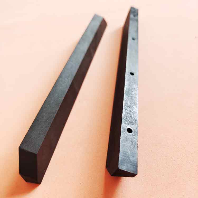
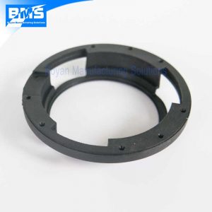
This plastic guide rail has solid and thick walls, there is no coring or grooves due to its limitations. There are 4 holes located along its length for mounting screws.
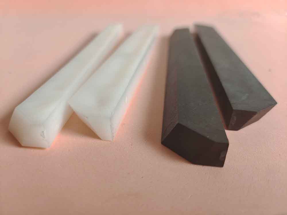
Part specification:
| Material | PP 50% LFT |
| Dimensions | 205*22.5*11 mm |
| Wall thickness | 11 mm |
| Weight | 60 grams |
| Color | black |
| Packaging | bulk in cartons |
Critical quality points
Sink mark and warpage
The wall thickness is 11 mm, it is not particularly thick. However, it has a cross-section that is almost square in shape, meaning the width is close to the thickness. As a result, there will be consequent warping or sinking on the surface.
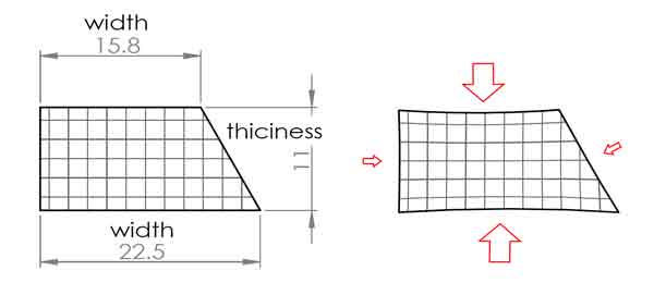
The choosing of material
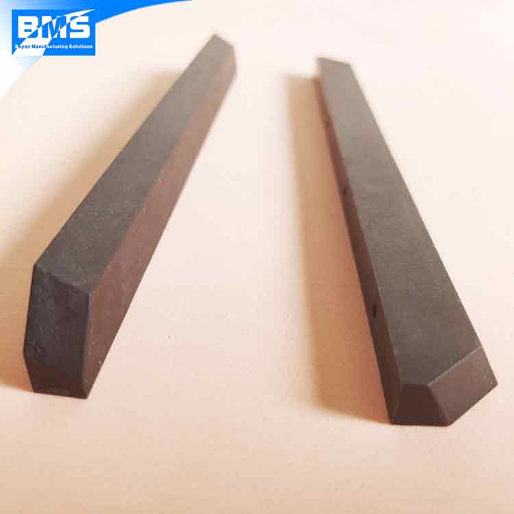
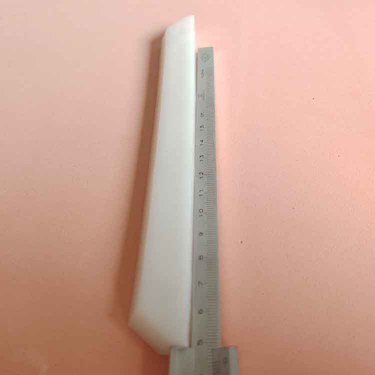
We first used HDPE to make the parts, as you can clearly see a sunken area on the picture. Moreover, the parts are a bit bent.
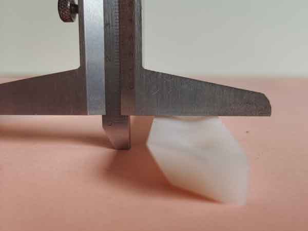
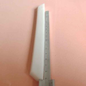
Later we tried another material, the enhanced PP with long glass fibers (PP 50% LFT), which has better dimensional stability, they appeared to be much better. Not only the sinking is a lot less, but also its straightness is within an acceptable level.
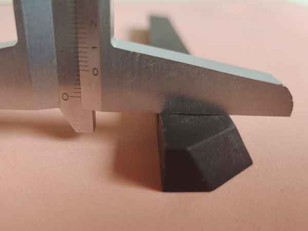
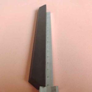
Since the second material (PP 50% LFT) has a smaller shrinkage rate than the first one (HDPE), we had to modify the mold to make the mold cavity about 1mm longer on the length of 205 mm, the location of holes also need to be adjusted. We kind of expected this prior to mold production and left some room for modification, so it does not cost as much as it might have taken.
Tight tolerance for the hole to hole distance
As far as structural components are concerned, the location of the holes is often critical for registration of the mating components.
For this part, the hole to hole distances needs to be held within +/-0.15 to +/-0.40mm.
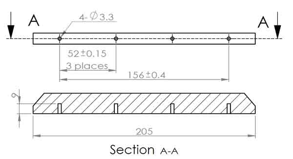
We firstly did not make the holes but just smaller indents to check how much the shrinkage affects the hole locations. The holes are added after we have made samples. As a result, the hole locations are all made within their tolerances.
