TPE overmolding of a power tool handle
TPE overmolding is the process of injection the molten Thermoplastic Elastomer (TPE) onto the surface of a pre-molded rigid plastic piece, which is known as the substrate, and form a one integral part consists of 2 or more thermoplastic material. TPE overmolding is quite common for manufacturers who produce power tool handles, hand tool handles, toothbrushes and other similar products.
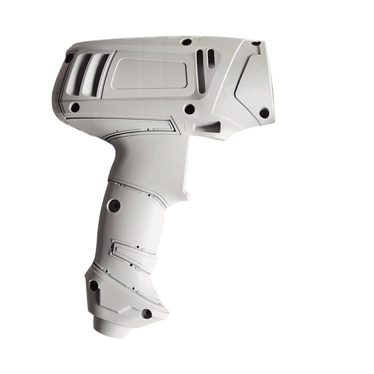
TPE overmolding will provide a soft touch, increase the hand grip, give the product a stylish appearance if designed properly. However, the downside is it makes recycling more difficult because you have to separate the different materials for each of them to be recycled.
Critical quality points
- Good appearance: clean edge, minimus flashes or trailing edge, pleasing color and glossiness.
- sufficient bonding strength: Sufficient temperature is required to form the required chemical bond, it is important to properly control the molding parameters, and have an appropriate product design.
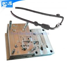
This is a power tool handle done by TPE overmolding on a substrate of PA6+GF30.
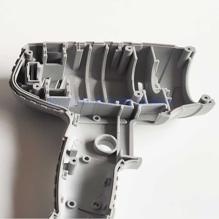
There are small grooves on the substrate locating near the edge of the TPE area, the purpose is quite straightforward, which is to create mechanical interlocks to help improve the bonding strength.
These parts are produced by insert molding in regular horizontal injection molding machines. First, the substrates are molded, then after a few days, the substrates will be used for the overmolding with the second mold. This process is done manually.
The substrates shall be kept clean, free from dirt, debris, oil, and mold release agents before being used. However, we do not heat the substrates, even in winter. We can still get a good adhesion strength.
As you can see, the overmolding is quite nicely done, there are almost no peeling, frayings, flashes and delamination found.
Part specification
| Material | PA6 GF 3o / TPE |
| Dimensions | 230*310*38mm |
| Net weight | 150 grams |
| Mold cavity number | 2 cavities |
| Mold steel | 718H |
| Runner type | cold runner |
Mold cost: $10,000
2 molds are required, one for the substrate, the other for the TPE over-molding. Each mold has 2 cavities
The mold material is 718H.
A short video: